ELECTRICAL KEY OSCILLATOR (for Front Floor) REMOVAL

Tech Tips
-
Use the same procedure for RHD and LHD vehicles.
-
The procedure listed below is for LHD vehicles.
-
REMOVE NO. 2 INSTRUMENT PANEL FINISH PANEL CUSHION
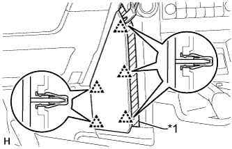
Text in Illustration *1 Protective Tape
-
Put protective tape around the No. 2 instrument panel finish panel cushion.
-
Using a moulding remover, detach the 5 clips and remove the No. 2 instrument panel finish panel cushion.
-
-
REMOVE NO. 1 INSTRUMENT PANEL FINISH PANEL CUSHION
Tech Tips
Use the same procedure described for the No. 2 instrument panel finish panel cushion.
-
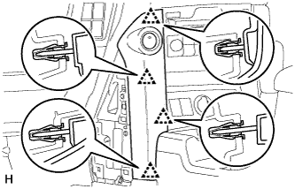
REMOVE INSTRUMENT PANEL FINISH PANEL END LH
-
Detach the 4 clips and remove the instrument panel finish panel end.
-
-
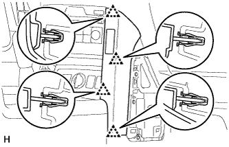
REMOVE INSTRUMENT PANEL FINISH PANEL END RH
-
Detach the 4 clips.
-
Disconnect the connector and remove the instrument panel finish panel end.
-
-
REMOVE FRONT CONSOLE UPPER PANEL GARNISH
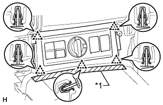
Text in Illustration *1 Protective Tape
-
Put protective tape around the front console upper panel garnish.
-
Detach the 5 clips.
-
Disconnect each connector and remove the front console upper panel garnish.
-
-
REMOVE SHIFT LEVER KNOB SUB-ASSEMBLY (for Automatic Transmission)
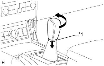
Text in Illustration *1 Shifting Hole Cover
-
Move the shifting hole cover downward.
-
Twist the shift lever knob in the direction indicated by the arrow and remove it.
-
-
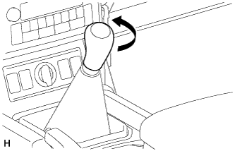
REMOVE SHIFT LEVER KNOB SUB-ASSEMBLY (for Manual Transmission)
-
Twist the shift lever knob in the direction indicated by the arrow and remove it.
-
-
REMOVE CONSOLE PANEL SUB-ASSEMBLY (for Automatic Transmission)
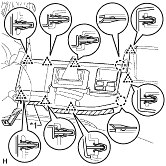
Text in Illustration *1 Protective Tape
-
Put protective tape around the console panel.
-
Using a moulding remover, detach the 8 clips and 2 claws.
-
Disconnect each connector and remove the console panel.
-
-
REMOVE CONSOLE PANEL SUB-ASSEMBLY (for Manual Transmission)
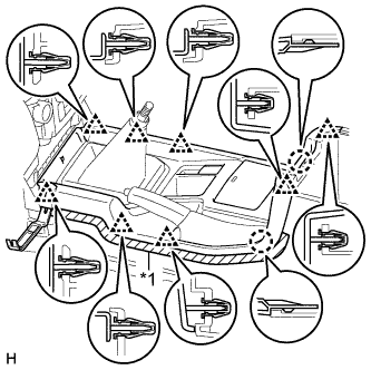
Text in Illustration *1 Protective Tape
-
Put protective tape around the console panel.
-
Using a moulding remover, detach the 8 clips and 2 claws.
-
Disconnect each connector and remove the console panel.
-
-
REMOVE INDOOR NO. 1 ELECTRICAL KEY ANTENNA ASSEMBLY
-
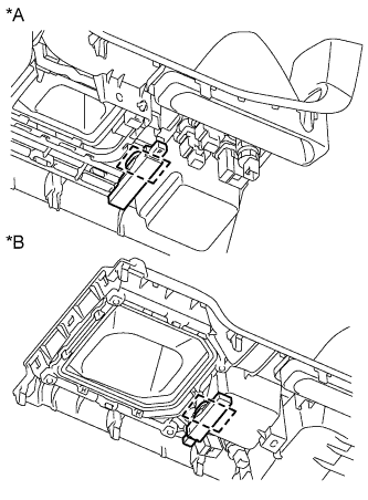
Text in Illustration *A for Automatic Transmission *B for Manual Transmission Detach the clamp and remove the indoor No. 1 electrical key antenna assembly.
-