THEFT DETERRENT SYSTEM, Diagnostic DTC:B2762, B2764

| DTC Code | DTC Name |
|---|---|
| B2762 | Intrusion Sensor Signal Circuit Malfunction |
| B2764 | Short to GND in Intrusion Sensor Signal Circuit |
DESCRIPTION
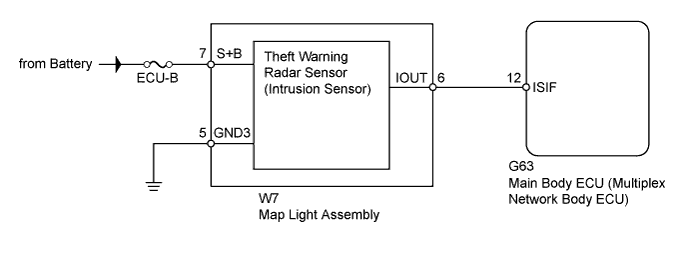
The theft warning radar sensor (intrusion sensor) conducts a self-diagnosis immediately after power is supplied to the sensor (when the theft deterrent system is set).
If a malfunction is detected in the IOUT line, the main body ECU stores DTC B2762.
DTC B2764 is stored when terminal IOUT of the theft warning radar sensor (intrusion sensor) has not received a signal for 5 seconds or more.
| DTC Code | DTC Detection Condition | Trouble Area |
|---|---|---|
| B2762 | After a normal/trouble signal is output from the theft warning radar sensor (intrusion sensor) as a result of self-diagnosis, either of the following malfunctions is detected:
|
|
| B2764 | After a normal/trouble signal is output from the theft warning radar sensor (intrusion sensor) as a result of self-diagnosis, the following malfunction is detected: Terminal IOUT of the theft warning radar sensor (intrusion sensor) has not received a signal for 5 seconds or more. |
|
WIRING DIAGRAM
INSPECTION PROCEDURE
Note
Inspect the fuses for circuits related to this system before performing the following inspection procedure.
PROCEDURE
-
CHECK HARNESS AND CONNECTOR (MAP LIGHT - BATTERY AND BODY GROUND)
-
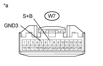
Text in Illustration *a Front view of wire harness connector
(to Map Light Assembly)
Disconnect the W7 light connector.
-
Measure the resistance according to the value(s) in the table below.
Standard Resistance Tester Connection Condition Specified Condition W7-5 (GND3) - Body ground Always Below 1 Ω -
Measure the voltage according to the value(s) in the table below.
Standard Voltage Tester Connection Condition Specified Condition W7-7 (S+B) - Body ground Always 11 to 14 V
NG 
REPAIR OR REPLACE HARNESS OR CONNECTOR
OK 
-
-
CHECK HARNESS AND CONNECTOR (MAP LIGHT - MAIN BODY ECU)
-
Disconnect the W7 light connector.
-
Disconnect the G63 ECU connector.
-
Measure the resistance according to the value(s) in the table below.
Standard Resistance Tester Connection Condition Specified Condition W7-6 (IOUT) - G63-12 (ISIF) Always Below 1 Ω W7-6 (IOUT) or G63-12 (ISIF) - Body ground Always 10 kΩ or higher
NG
REPAIR OR REPLACE HARNESS OR CONNECTOR
OK
-
-
CHECK MAP LIGHT ASSEMBLY (THEFT WARNING RADAR SENSOR)
-
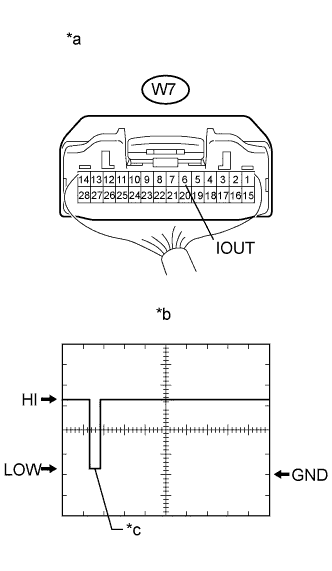
Text in Illustration *a Component with harness connected
(Map Light Assembly)
*b Waveform *c Initial Response Using an oscilloscope, check the waveform.
Measurement Condition Item Content Tester Connection W7-6 (IOUT) - Body ground Tool Setting 2 V/DIV., 100 ms./DIV. Condition Immediately after theft deterrent system set Tech Tips
-
If the intrusion sensor is normal when the map light receives a HI input signal from the main body ECU, the sensor outputs the initial response.
-
When the input signal from the main body ECU is LOW and does not change, the main body ECU may be malfunctioning.
OK Initial response occurs (refer to illustration). Result Result Proceed to OK A NG (Signal is LOW and does not change) B NG (Signal is HIGH and does not change) C -
B
REPLACE MAIN BODY ECU (MULTIPLEX NETWORK BODY ECU) Click here
C
REPLACE MAP LIGHT ASSEMBLY (THEFT WARNING RADAR SENSOR) Click here
A 
REPLACE MAIN BODY ECU (MULTIPLEX NETWORK BODY ECU) Click here
-