ENGINE IMMOBILISER SYSTEM (w/o Entry and Start System), Diagnostic DTC:B2797

| DTC Code | DTC Name |
|---|---|
| B2797 | Communication Malfunction No. 1 |
DESCRIPTION
This DTC is stored when a communication error occurs between the transponder key amplifier and transponder key ECU assembly. Some possible reasons for the communication error are: 1) 2 or more ignition keys are positioned too close together, or 2) noise is occurring in the communication line.
| DTC Code | DTC Detection Condition | Trouble Area |
|---|---|---|
| B2797 | 2 or more ignition keys are positioned too close to each other or noise occurs in the communication line. |
|
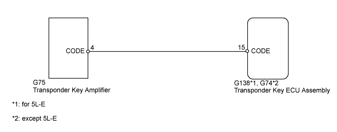
WIRING DIAGRAM
INSPECTION PROCEDURE
Note
When replacing the transponder key ECU assembly, refer to the Service Bulletin.
PROCEDURE
-
CHECK KEY
-
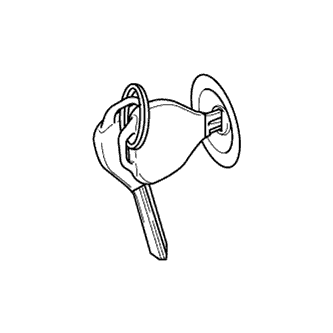
Check whether the ignition key being used is near other ignition keys, as shown in the illustration. Also, check whether a key ring is in contact with the key grip.
Result Result Proceed to Key is near other keys and/or key ring is in contact with key grip A Key is not near other keys and key ring is not in contact with key grip B
B 
CHECK HARNESS AND CONNECTOR (TRANSPONDER KEY ECU - TRANSPONDER KEY AMPLIFIER) Click here
A 
-
-
CHECK FOR DTC
-
Separate the keys from each other or remove the key ring.
-
Clear the DTCs Click here.
-
Insert a key into the ignition key cylinder, and then remove it. Repeat this for all the other keys.
-
Check that no DTC is output Click here.
OK DTC B2797 is not output.
NG
CHECK HARNESS AND CONNECTOR (TRANSPONDER KEY ECU - TRANSPONDER KEY AMPLIFIER) Click here
OK 
END
-
-
CHECK HARNESS AND CONNECTOR (TRANSPONDER KEY ECU - TRANSPONDER KEY AMPLIFIER)
-
Disconnect the G138*1 or G74*2 ECU connector.
-
*1: for 5L-E
-
*2: except 5L-E
-
-
Disconnect the G75 amplifier connector.
-
Measure the resistance according to the value(s) in the table below.
Standard Resistance for 5L-E Tester Connection Condition Specified Condition G138-15 (CODE) - G75-4 (CODE) Always Below 1 Ω G138-15 (CODE) or G75-4 (CODE) - Body ground Always 10 kΩ or higher except 5L-E Tester Connection Condition Specified Condition G74-15 (CODE) - G75-4 (CODE) Always Below 1 Ω G74-15 (CODE) or G75-4 (CODE) - Body ground Always 10 kΩ or higher
NG 
REPAIR OR REPLACE HARNESS OR CONNECTOR
OK
-
-
CHECK TRANSPONDER KEY ECU ASSEMBLY (NOISE)
-
*1: for 5L-E
-
*2: except 5L-E
-
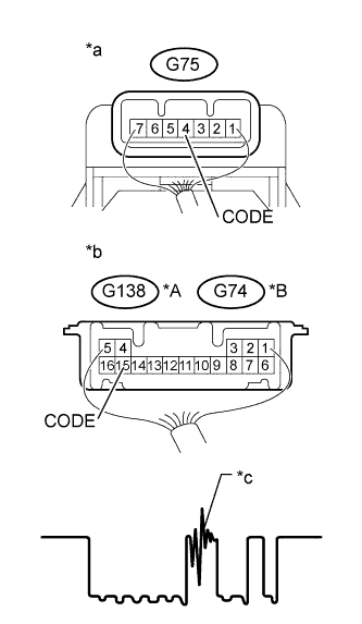
Text in Illustration *A for 5L-E *B except 5L-E *a Component with harness connected
(Transponder Key Amplifier)
*b Component with harness connected
(Transponder Key ECU Assembly)
*c Noise should not appear Using an oscilloscope, check for noise in the waveform between the terminals of the G75 amplifier connector and G138*1 or G74*2 ECU connector.
Measurement Condition Item Content Tester Connection G75-4 (CODE) - G138-15 (CODE)*1
G75-4 (CODE) - G74-15 (CODE)*2
Tool Setting 5 V/DIV., 20 ms./DIV. Condition Key inserted in ignition key cylinder OK No noise is present.
NG
FIND CAUSE OF NOISE AND REMOVE IT
OK
-
-
REPLACE TRANSPONDER KEY AMPLIFIER
-
Temporarily replace the transponder key amplifier with a new or normally functioning one Click here.
NEXT
-
-
CHECK WHETHER ENGINE STARTS
-
Check that the engine starts normally.
OK Engine starts.
NG
REPLACE TRANSPONDER KEY ECU ASSEMBLY
OK
END (TRANSPONDER KEY AMPLIFIER IS DEFECTIVE)
-