THEFT DETERRENT SYSTEM Security Indicator Light Circuit
DESCRIPTION
-
When the theft deterrent system is in the disarmed state, the security indicator light flashes continuously when the engine immobiliser system is set, and does not illuminate when the engine immobiliser system is not set.
When the theft deterrent system is in the armed state, the engine immobiliser system is automatically set and the security indicator light flashes continuously.
When the theft deterrent system is in the arming preparation state or alarm sounding state, the main body ECU causes the security indicator light to be illuminated.
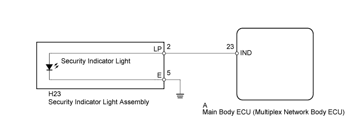
WIRING DIAGRAM
INSPECTION PROCEDURE
PROCEDURE
-
PERFORM ACTIVE TEST USING INTELLIGENT TESTER (SECURITY INDICATOR LIGHT)
-
Operate the intelligent tester according to the steps on the display and select Active Test Click here.
Main Body Tester Display Test Part Control Range Diagnostic Note Security Indicator Security indicator light ON/OFF The test is possible when the following conditions are met:
-
The key is in the cabin*1
-
The engine switch on (IG)*1
-
The key is in the ignition key cylinder*2
-
*1: w/ Entry and Start System
-
*2: w/o Entry and Start System
OK Security indicator light can be turned on and off using the intelligent tester. -
NG 
INSPECT SECURITY INDICATOR LIGHT ASSEMBLY Click here
OK 
PROCEED TO NEXT SUSPECTED AREA SHOWN IN PROBLEM SYMPTOMS TABLE Click here
-
-
INSPECT SECURITY INDICATOR LIGHT ASSEMBLY
-
Remove the security indicator light Click here.
-
Apply battery voltage between the terminals of the security indicator light assembly and check that the security indicator light illuminates.
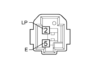
OK Measurement Condition Specified Condition Battery positive (+) → 2 (LP)
Battery negative (-) → 5 (E)
Security indicator light illuminates
NG 
REPLACE SECURITY INDICATOR LIGHT ASSEMBLY Click here
OK 
-
-
CHECK HARNESS AND CONNECTOR (SECURITY INDICATOR LIGHT - MAIN BODY ECU AND BODY GROUND)
-
Disconnect the H23 light connector.
-
Remove the main body ECU Click here.
-
Measure the resistance according to the value(s) in the table below.
Standard Resistance Tester Connection Condition Specified Condition H23-2 (LP) - A-23 (IND) Always Below 1 Ω H23-5 (E) - Body ground Always Below 1 Ω H23-2 (LP) or A-23 (IND) - Body ground Always 10 kΩ or higher
NG
REPAIR OR REPLACE HARNESS OR CONNECTOR
OK
REPLACE MAIN BODY ECU (MULTIPLEX NETWORK BODY ECU) Click here
-