THEFT DETERRENT SYSTEM Security Horn Circuit
DESCRIPTION
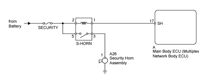
When the theft deterrent system is in the alarm sounding state, the main body ECU outputs a signal repeatedly at 0.4 second intervals, causing the security horn assembly to sound.
WIRING DIAGRAM
INSPECTION PROCEDURE
Note
Inspect the fuses for circuits related to this system before performing the following inspection procedure.
PROCEDURE
-
PERFORM ACTIVE TEST USING INTELLIGENT TESTER (SECURITY HORN)
-
Operate the intelligent tester according to the steps on the display and select Active Test Click here.
Main Body Tester Display Test Part Control Range Diagnostic Note Security Horn Security horn ON/OFF - OK Security horn operates normally.
NG 
INSPECT S-HORN RELAY Click here
OK 
PROCEED TO NEXT SUSPECTED AREA SHOWN IN PROBLEM SYMPTOMS TABLE Click here
-
-
INSPECT S-HORN RELAY
-
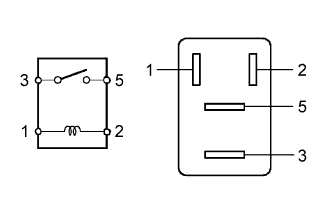
Remove the S-HORN relay from the engine room relay block.
-
Measure the resistance according to the value(s) in the table below.
Standard Resistance Tester Connection Condition Specified Condition 3 - 5 Battery voltage is not applied to terminals 1 and 2 10 kΩ or higher 3 - 5 Battery voltage is applied to terminals 1 and 2 Below 1 Ω
NG 
REPLACE S-HORN RELAY
OK 
-
-
INSPECT SECURITY HORN ASSEMBLY
-
Remove the security horn Click here.
-
Apply battery voltage to the horn connector and check the operation of the horn.
OK Measurement Condition Specified Condition Battery positive (+) → Terminal 1
Battery negative (-) → Horn bracket
Horn sounds
NG
REPLACE SECURITY HORN ASSEMBLY Click here
OK
-
-
CHECK HARNESS AND CONNECTOR (ENGINE ROOM RELAY BLOCK - MAIN BODY ECU AND SECURITY HORN)
-
Remove the S-HORN relay from the engine room relay block.
-
Remove the main body ECU Click here.
-
Disconnect the A26 horn connector.
-
Measure the resistance according to the value(s) in the table below.
Standard Resistance Tester Connection Condition Specified Condition Relay block S-HORN relay terminal 1 - A-17 (SH) Always Below 1 Ω Relay block S-HORN relay terminal 3 - A26-1 Always Below 1 Ω A-17 (SH) - Body ground Always 10 kΩ or higher A26-1 - Body ground Always 10 kΩ or higher -
Measure the voltage according to the value(s) in the table below.
Standard Voltage Tester Connection Condition Specified Condition Relay block S-HORN relay terminal 2 - Body ground Always 11 to 14 V Relay block S-HORN relay terminal 5 - Body ground Always 11 to 14 V
NG
REPAIR OR REPLACE HARNESS OR CONNECTOR
OK
REPLACE MAIN BODY ECU (MULTIPLEX NETWORK BODY ECU) Click here
-