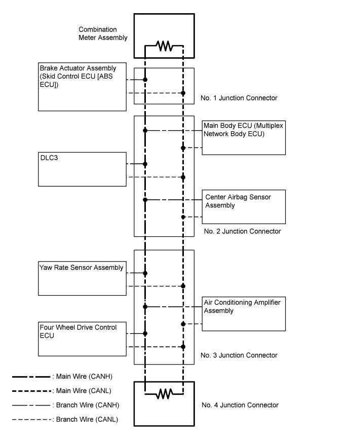
CAN COMMUNICATION SYSTEM (for RHD without Entry and Start System) SYSTEM DIAGRAM

-
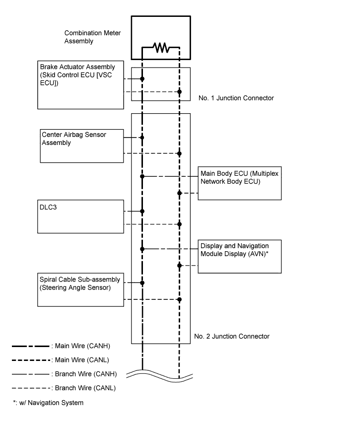
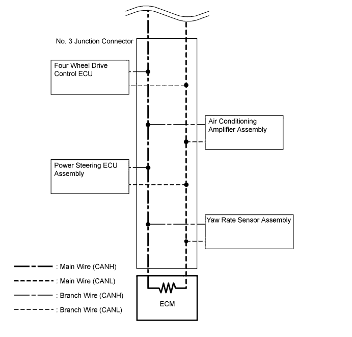
SYSTEM DIAGRAM
No. ECU/Sensor Name 1 Combination meter assembly 2 Main body ECU (multiplex network body ECU) 3 DLC3 4 Yaw rate sensor assembly 5 Center airbag sensor assembly 6 Display and navigation module display (AVN)* 7 Spiral cable sub-assembly (steering angle sensor) 8 Power steering ECU assembly 9 Air conditioning amplifier assembly 10 Four wheel drive control ECU 11 Brake actuator assembly (skid control ECU [VSC ECU]) 12 ECM 13 Brake actuator assembly (skid control ECU [ABS ECU]) 14 No. 4 junction connector
-
*: w/ Navigation System
-
-
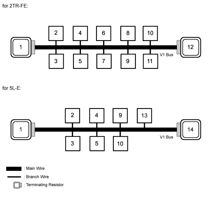
V1 BUS (for 2TR-FE)
-
V1 BUS (for 5L-E)