LIN COMMUNICATION SYSTEM, Diagnostic DTC:B2662

| DTC Code | DTC Name |
|---|---|
| B2662 | Lost Communication with Clock/Outside Temperature Display |
DESCRIPTION
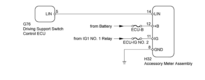
This DTC is stored when LIN communication between the driving support switch control ECU and accessory meter assembly stops for 10 seconds or more.
| DTC Code | DTC Detection Condition | Trouble Area |
|---|---|---|
| B2662 | No communication between the driving support switch control ECU and accessory meter assembly for 10 seconds or more. |
|
WIRING DIAGRAM
INSPECTION PROCEDURE
Note
-
When using the intelligent tester with the ignition switch off to troubleshoot:
Connect the intelligent tester to the vehicle and turn a courtesy light switch on and off at 1.5 second intervals until communication between the intelligent tester and vehicle begins.
-
Inspect the fuses and bulbs for circuits related to this system before performing the following inspection procedure.
PROCEDURE
-
CLEAR DTC
-
Clear the DTCs Click here.
NEXT 
-
-
CHECK FOR DTC
-
Check for DTCs Click here.
OK DTC B2662 is not output.
NG 
CHECK HARNESS AND CONNECTOR (DRIVING SUPPORT SWITCH CONTROL ECU - ACCESSORY METER) Click here
OK 
USE SIMULATION METHOD TO CHECK Click here
-
-
CHECK HARNESS AND CONNECTOR (DRIVING SUPPORT SWITCH CONTROL ECU - ACCESSORY METER)
-
Disconnect the G76 driving support switch control ECU connector.
-
Disconnect the H32 accessory meter assembly connector.
-
Measure the resistance according to the value(s) in the table below.
Standard Resistance Tester Connection Condition Specified Condition G76-5 (LIN) - H32-14 (LIN) Always Below 1 Ω G76-5 (LIN) or H32-14 (LIN) - Body ground Always 10 kΩ or higher
NG 
REPAIR OR REPLACE HARNESS OR CONNECTOR
OK
-
-
CHECK HARNESS AND CONNECTOR (ACCESSORY METER - BATTERY AND BODY GROUND)
-
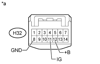
Text in Illustration *a Front view of wire harness connector
(to Accessory Meter Assembly)
Disconnect the H32 accessory meter assembly connector.
-
Measure the resistance according to the value(s) in the table below.
Standard Resistance Tester Connection Condition Specified Condition H32-8 (GND) - Body ground Always Below 1 Ω -
Measure the voltage according to the value(s) in the table below.
Standard Voltage Tester Connection Switch Condition Specified Condition H32-12 (+B) - Body ground Always 11 to 14 V H32-11 (IG) - Body ground Ignition switch ON 11 to 14 V
NG
REPAIR OR REPLACE HARNESS OR CONNECTOR
OK
-
-
REPLACE ACCESSORY METER ASSEMBLY
-
Temporarily replace the accessory meter assembly with a new or normally functioning one Click here.
NEXT
-
-
CLEAR DTC
-
Clear the DTCs Click here.
NEXT
-
-
CHECK FOR DTC
-
Check for DTCs Click here.
OK DTC B2662 is not output.
NG
REPLACE DRIVING SUPPORT SWITCH CONTROL ECU Click here
OK
END (ACCESSORY METER IS DEFECTIVE)
-