LIN COMMUNICATION SYSTEM, Diagnostic DTC:B2325

| DTC Code | DTC Name |
|---|---|
| B2325 | LIN Communication Bus Malfunction |
DESCRIPTION
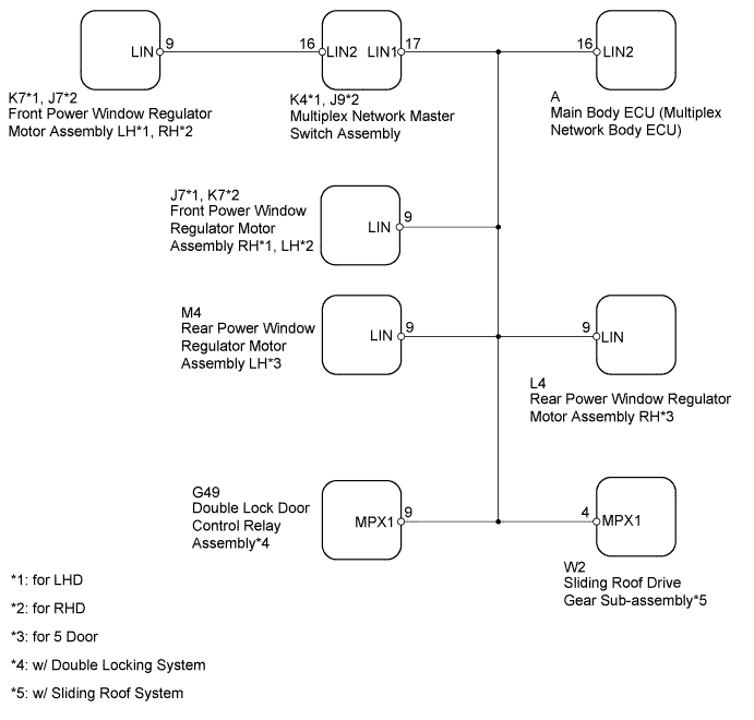
The main body ECU (multiplex network body ECU) intermittently monitors the LIN communication bus between the components related to the doors, double lock door control relay assembly*1 and sliding roof drive gear sub-assembly*2. DTC B2325 is stored when a malfunction in the LIN communication bus between the components related to the doors, double lock door control relay assembly*1 and sliding roof drive gear sub-assembly*2 is detected consecutively 3 times.
-
*1: w/ Double Locking System
-
*2: w/ Sliding Roof System
| DTC Code | DTC Detection Condition | Trouble Area |
|---|---|---|
| B2325 | The main body ECU (multiplex network body ECU) detects a malfunction in the LIN communication bus between components related to the doors, double lock door control relay assembly*2 and sliding roof drive gear sub-assembly*3 consecutively 3 times. |
|
-
*1: for 5 Door
-
*2: w/ Double Locking System
-
*3: w/ Sliding Roof System
WIRING DIAGRAM
INSPECTION PROCEDURE
Note
When using the intelligent tester with the ignition switch off to troubleshoot:
Connect the intelligent tester to the vehicle and turn a courtesy light switch on and off at 1.5 second intervals until communication between the intelligent tester and vehicle begins.
Tech Tips
When DTC B2325 and a LIN communication stop DTC are output simultaneously, first perform troubleshooting for the LIN communication stop DTC. Then perform troubleshooting for DTC B2325.
PROCEDURE
-
CLEAR DTC
-
Clear the DTCs Click here.
NEXT 
-
-
CHECK FOR DTC
-
Check for DTCs Click here.
OK DTC B2325 is not output.
NG 
CHECK HARNESS AND CONNECTOR (MAIN BODY ECU - MULTIPLEX NETWORK MASTER SWITCH) Click here
OK 
USE SIMULATION METHOD TO CHECK Click here
-
-
CHECK HARNESS AND CONNECTOR (MAIN BODY ECU - MULTIPLEX NETWORK MASTER SWITCH)
-
Remove the main body ECU (multiplex network body ECU) from the driver side junction block assembly Click here.
-
Disconnect the K4*1 or J9*2 multiplex network master switch assembly connector.
-
*1: for LHD
-
*2: for RHD
-
-
Measure the resistance according to the value(s) in the table below.
Standard Resistance for LHD Tester Connection Condition Specified Condition A-16 (LIN2) - K4-17 (LIN1) Always Below 1 Ω A-16 (LIN2) or K4-17 (LIN1) - Body ground Always 10 kΩ or higher for RHD Tester Connection Condition Specified Condition A-16 (LIN2) - J9-17 (LIN1) Always Below 1 Ω A-16 (LIN2) or J9-17 (LIN1) - Body ground Always 10 kΩ or higher
NG 
REPAIR OR REPLACE HARNESS OR CONNECTOR
OK
-
-
CLEAR DTC
-
*1: for LHD
-
*2: for RHD
-
Install the main body ECU (multiplex network body ECU) to the driver side junction block assembly Click here.
-
Reconnect the K4*1 or J9*2 multiplex network master switch assembly connector.
-
Disconnect the K7*1 or J7*2 front power window regulator motor assembly connector.
-
Clear the DTCs Click here.
NEXT
-
-
CHECK FOR DTC
-
Check for DTCs Click here.
Result Result Proceed to DTC B2325 is output A DTC B2325 is not output B
B
REPLACE FRONT POWER WINDOW REGULATOR MOTOR ASSEMBLY Click here
A
-
-
CLEAR DTC
-
*1: for LHD
-
*2: for RHD
-
Connect the K7*1 or J7*2 front power window regulator motor assembly connector.
-
Disconnect the K4*1 or J9*2 multiplex network master switch assembly connector.
-
Clear the DTCs Click here.
NEXT
-
-
CHECK FOR DTC
-
Check for DTCs Click here.
Result Result Proceed to DTC B2325 is output A DTC B2325 is not output B
B
REPLACE MULTIPLEX NETWORK MASTER SWITCH ASSEMBLY Click here
A
-
-
CLEAR DTC
-
*1: for LHD
-
*2: for RHD
-
Connect the K4*1 or J9*2 multiplex network master switch assembly connector.
-
Disconnect the J7*1 or K7*2 front power window regulator motor assembly connector.
-
Clear the DTCs Click here.
NEXT
-
-
CHECK FOR DTC
-
Check for DTCs Click here.
Result Result Proceed to DTC B2325 is output (for 5 Door) A DTC B2325 is output (for 3 Door, w/ Double Locking System) B DTC B2325 is output (for 3 Door, w/o Double Locking System, w/ Sliding Roof System) C DTC B2325 is output (for 3 Door, w/o Double Locking System, w/o Sliding Roof System) D DTC B2325 is not output E
B
CLEAR DTC Click here
C
CLEAR DTC Click here
D
REPLACE MAIN BODY ECU (MULTIPLEX NETWORK BODY ECU) Click here
E
OTHERS FRONT POWER WINDOW REGULATOR MOTOR ASSEMBLY Click here
A
-
-
CLEAR DTC
-
Connect the J7*1 or K7*2 front power window regulator motor assembly connector.
-
*1: for LHD
-
*2: for RHD
-
-
Disconnect the L4 rear power window regulator motor assembly RH connector.
-
Clear the DTCs Click here.
NEXT
-
-
CHECK FOR DTC
-
Check for DTCs Click here.
Result Result Proceed to DTC B2325 is output A DTC B2325 is not output B
B
REPLACE REAR POWER WINDOW REGULATOR MOTOR ASSEMBLY RH Click here
A
-
-
CLEAR DTC
-
Connect the L4 rear power window regulator motor assembly RH connector.
-
Disconnect the M4 rear power window regulator motor assembly LH connector.
-
Clear the DTCs Click here.
NEXT
-
-
CHECK FOR DTC
-
Check for DTCs Click here.
Result Result Proceed to DTC B2325 is output (w/ Double Locking System) A DTC B2325 is output (w/o Double Locking System, w/ Sliding Roof System) B DTC B2325 is output (w/o Double Locking System, w/o Sliding Roof System) C DTC B2325 is not output D
B
CLEAR DTC Click here
C
CHECK MAIN BODY ECU (MULTIPLEX NETWORK BODY ECU) Click here
D
REPLACE REAR POWER WINDOW REGULATOR MOTOR ASSEMBLY LH Click here
A
-
-
CLEAR DTC
-
Connect the M4 rear power window regulator motor assembly LH connector.
-
Disconnect the G49 double lock door control relay assembly connector.
-
Clear the DTCs Click here.
NEXT
-
-
CHECK FOR DTC
-
Check for DTCs Click here.
Result Result Proceed to DTC B2325 is output (w/ Sliding Roof System) A DTC B2325 is output (w/o Sliding Roof System) B DTC B2325 is not output C
B
REPLACE MAIN BODY ECU (MULTIPLEX NETWORK BODY ECU) Click here
C
REPLACE DOUBLE LOCK DOOR CONTROL RELAY ASSEMBLY Click here
A
-
-
CLEAR DTC
-
w/ Double Locking System:
-
Connect the G49 double lock door control relay assembly connector.
-
-
w/o Double Locking System:
-
Connect the M4 rear power window regulator motor assembly LH connector.
-
-
Disconnect the W2 sliding roof drive gear sub-assembly connector.
-
Clear the DTCs Click here.
NEXT
-
-
CHECK FOR DTC
-
Check for DTCs Click here.
Result Result Proceed to DTC B2325 is output A DTC B2325 is not output B
B
REPLACE SLIDING ROOF DRIVE GEAR SUB-ASSEMBLY Click here
A
REPLACE MAIN BODY ECU (MULTIPLEX NETWORK BODY ECU) Click here
-
-
CLEAR DTC
-
Connect the J7*1 or K7*2 front power window regulator motor assembly connector.
-
*1: for LHD
-
*2: for RHD
-
-
Disconnect the G49 double lock door control relay assembly connector.
-
Clear the DTCs Click here.
NEXT
-
-
CHECK FOR DTC
-
Check for DTCs Click here.
Result Result Proceed to DTC B2325 is output (w/ Sliding Roof System) A DTC B2325 is output (w/o Sliding Roof System) B DTC B2325 is not output C
B
REPLACE MAIN BODY ECU (MULTIPLEX NETWORK BODY ECU) Click here
C
REPLACE DOUBLE LOCK DOOR CONTROL RELAY ASSEMBLY Click here
A
-
-
CLEAR DTC
-
w/ Double Locking System:
-
Connect the G49 double lock door control relay assembly connector.
-
-
w/o Double Locking System:
-
Connect the J7*1 or K7*2 front power window regulator motor assembly connector.
-
*1: for LHD
-
*2: for RHD
-
-
-
Disconnect the W2 sliding roof drive gear sub-assembly connector.
-
Clear the DTCs Click here.
NEXT
-
-
CHECK FOR DTC
-
Check for DTCs Click here.
Result Result Proceed to DTC B2325 is output A DTC B2325 is not output B
B
REPLACE SLIDING ROOF DRIVE GEAR SUB-ASSEMBLY Click here
A
REPLACE MAIN BODY ECU (MULTIPLEX NETWORK BODY ECU) Click here
-