LIN COMMUNICATION SYSTEM TERMINALS OF ECU

-
CHECK MAIN BODY ECU (MULTIPLEX NETWORK BODY ECU) AND DRIVER SIDE JUNCTION BLOCK ASSEMBLY
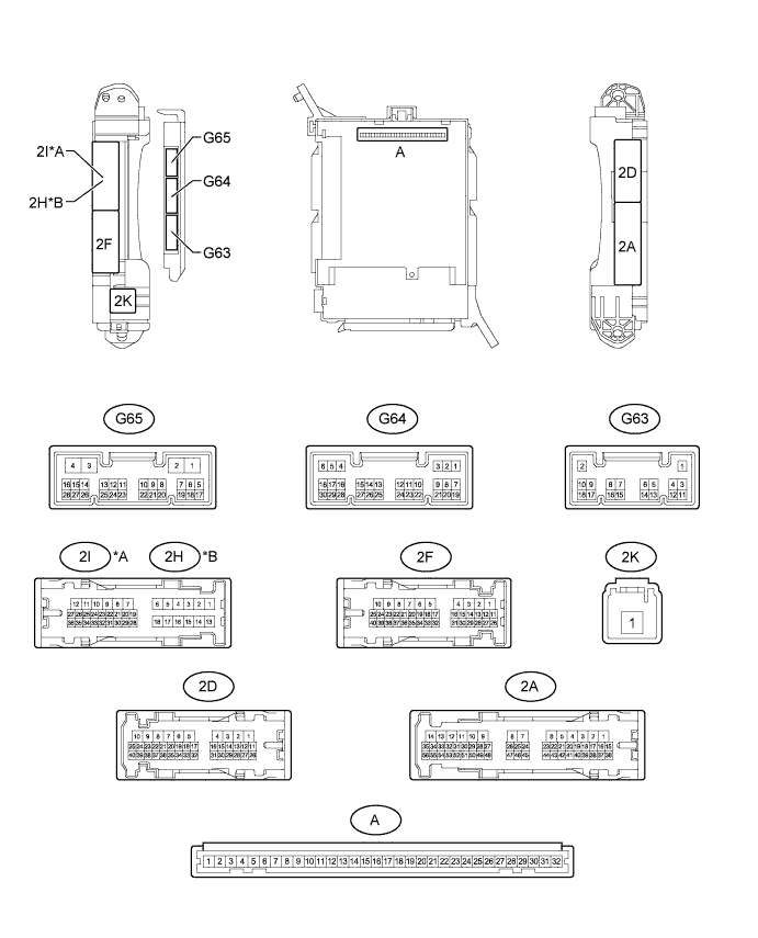
Text in Illustration *A for LHD *B for RHD
-
Remove the main body ECU (multiplex network body ECU) from the driver side junction block assembly Click here.
-
Measure the resistance and voltage according to the value(s) in the table below.
Terminal No. (Symbol) Wiring Color Terminal Description Condition Specified Condition G63-3 (GND2) - Body ground W-B - Body ground Ground Always Below 1 Ω A-11 (GND1) - Body ground None - Body ground Ground Always Below 1 Ω A-30 (BECU) - Body ground None - Body ground Battery power supply Always 11 to 14 V A-32 (IG) - Body ground None - Body ground IG power supply Ignition switch ON 11 to 14 V If the result is not as specified, there may be a malfunction on the wire harness side.
-
-
CHECK MULTIPLEX NETWORK MASTER SWITCH ASSEMBLY
-
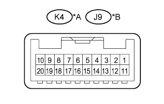
Text in Illustration *A for LHD *B for RHD Disconnect the K4*1 or J9*2 multiplex network master switch assembly connector.
-
*1: for LHD
-
*2: for RHD
-
-
Measure the resistance and voltage according to the value(s) in the table below.
for LHD Terminal No. (Symbol) Wiring Color Terminal Description Condition Specified Condition K4-12 (GND) - Body ground W-B - Body ground Ground Always Below 1 Ω K4-11 (B) - Body ground L - Body ground Battery power supply Always 11 to 14 V for RHD Terminal No. (Symbol) Wiring Color Terminal Description Condition Specified Condition J9-12 (GND) - Body ground W-B - Body ground Ground Always Below 1 Ω J9-11 (B) - Body ground L - Body ground Battery power supply Always 11 to 14 V If the result is not as specified, there may be a malfunction on the wire harness side.
-
-
CHECK FRONT POWER WINDOW REGULATOR MOTOR ASSEMBLY LH
-
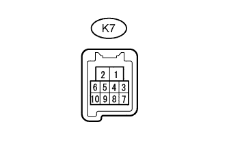
Disconnect the K7 front power window regulator motor assembly LH connector.
-
Measure the resistance and voltage according to the value(s) in the table below.
Terminal No. (Symbol) Wiring Color Terminal Description Condition Specified Condition K7-1 (GND) - Body ground W-B - Body ground Ground Always Below 1 Ω K7-2 (B) - Body ground R - Body ground*1
G - Body ground*2
Battery power supply Always 11 to 14 V
-
*1: for LHD
-
*2: for RHD
If the result is not as specified, there may be a malfunction on the wire harness side.
-
-
-
CHECK FRONT POWER WINDOW REGULATOR MOTOR ASSEMBLY RH
-
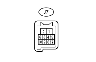
Disconnect the J7 front power window regulator motor assembly RH connector.
-
Measure the resistance and voltage according to the value(s) in the table below.
Terminal No. (Symbol) Wiring Color Terminal Description Condition Specified Condition J7-1 (GND) - Body ground W-B - Body ground Ground Always Below 1 Ω J7-2 (B) - Body ground G - Body ground*1
R - Body ground*2
Battery power supply Always 11 to 14 V
-
*1: for LHD
-
*2: for RHD
If the result is not as specified, there may be a malfunction on the wire harness side.
-
-
-
CHECK REAR POWER WINDOW REGULATOR MOTOR ASSEMBLY LH (for 5 Door)
-
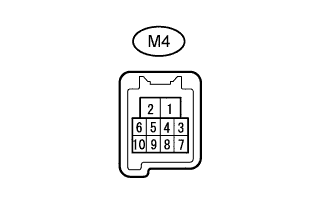
Disconnect the M4 rear power window regulator motor assembly LH connector.
-
Measure the resistance and voltage according to the value(s) in the table below.
Terminal No. (Symbol) Wiring Color Terminal Description Condition Specified Condition M4-1 (GND) - Body ground W-B - Body ground Ground Always Below 1 Ω M4-2 (B) - Body ground W - Body ground Battery power supply Always 11 to 14 V If the result is not as specified, there may be a malfunction on the wire harness side.
-
-
CHECK REAR POWER WINDOW REGULATOR MOTOR ASSEMBLY RH (for 5 Door)
-
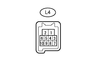
Disconnect the L4 rear power window regulator motor assembly RH connector.
-
Measure the resistance and voltage according to the value(s) in the table below.
Terminal No. (Symbol) Wiring Color Terminal Description Condition Specified Condition L4-1 (GND) - Body ground W-B - Body ground Ground Always Below 1 Ω L4-2 (B) - Body ground W - Body ground Battery power supply Always 11 to 14 V If the result is not as specified, there may be a malfunction on the wire harness side.
-
-
CHECK SLIDING ROOF DRIVE GEAR SUB-ASSEMBLY (w/ Sliding Roof System)
-
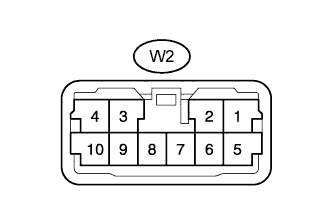
Disconnect the W2 sliding roof drive gear sub-assembly connector.
-
Measure the resistance and voltage according to the value(s) in the table below.
Terminal No. (Symbol) Wiring Color Terminal Description Condition Specified Condition W2-2 (E)- Body ground W-B - Body ground Ground Always Below 1 Ω W2-1 (B) - Body ground W - Body ground Battery power supply Always 11 to 14 V W2-5 (IG) - Body ground L - Body ground IG power supply Ignition switch ON 11 to 14 V If the result is not as specified, there may be a malfunction on the wire harness side.
-
-
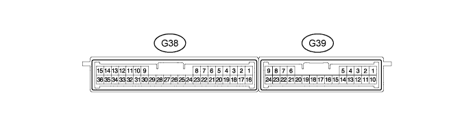
CHECK CERTIFICATION ECU (w/ Entry and Start System)
-
Disconnect the G38 certification ECU connector.
-
Measure the resistance and voltage according to the value(s) in the table below.
Terminal No. (Symbol) Wiring Color Terminal Description Condition Specified Condition G38-15 (E) - Body ground W-B - Body ground Ground Always Below 1 Ω G38-1 (+B) - Body ground V - Body ground Battery power supply Always 11 to 14 V G38-16 (IG) - Body ground W - Body ground IG power supply Ignition switch ON 11 to 14 V If the result is not as specified, there may be a malfunction on the wire harness side.
-
-
CHECK POWER MANAGEMENT CONTROL ECU (w/ Entry and Start System)
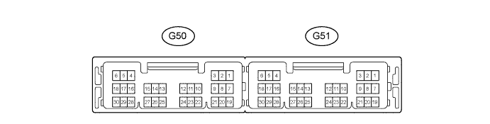
-
Disconnect the G51 power management control ECU connector.
-
Measure the resistance and voltage according to the value(s) in the table below.
Terminal No. (Symbol) Wiring Color Terminal Description Condition Specified Condition G51-6 (GND) - Body ground W-B - Body ground Ground Always Below 1 Ω G51-5 (GND2) - Body ground W-B - Body ground Ground Always Below 1 Ω G51-1 (AM22) - Body ground B - Body ground Battery power supply Always 11 to 14 V G51-2 (AM21) - Body ground B - Body ground Battery power supply Always 11 to 14 V
-
-
CHECK ID CODE BOX (w/ Entry and Start System)
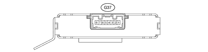
-
Disconnect the G37 ID code box connector.
-
Measure the resistance and voltage according to the value(s) in the table below.
Terminal No. (Symbol) Wiring Color Terminal Description Condition Specified Condition G37-8 (GND) - Body ground W-B - Body ground Ground Always Below 1 Ω G37-1 (+B) - Body ground V - Body ground Battery power supply Always 11 to 14 V If the result is not as specified, there may be a malfunction on the wire harness side.
-
-
CHECK STEERING LOCK ACTUATOR ASSEMBLY (STEERING LOCK ECU) (w/ Entry and Start System)
-
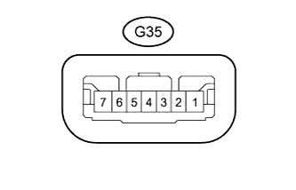
Disconnect the G35 steering lock actuator assembly (steering lock ECU) connector.
-
Measure the resistance and voltage according to the value(s) in the table below.
Terminal No. (Symbol) Wiring Color Terminal Description Condition Specified Condition G35-1 (GND) - Body ground W-B - Body ground Ground Always Below 1 Ω G35-7 (B) - Body ground G - Body ground Battery power supply Always 11 to 14 V G35-6 (IG2) - Body ground W - Body ground IG power supply Ignition switch ON 11 to 14 V If the result is not as specified, there may be a malfunction on the wire harness side.
-
-
CHECK AIR CONDITIONING AMPLIFIER ASSEMBLY
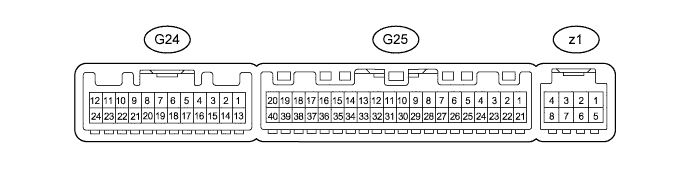
-
Disconnect the G25 air conditioning amplifier assembly connector.
-
Measure the resistance and voltage according to the value(s) in the table below.
Terminal No. (Symbol) Wiring Color Terminal Description Condition Specified Condition G25-14 (GND) - Body ground W-B - Body ground Ground Always Below 1 Ω G25-21 (B) - Body ground V - Body ground Battery power supply Always 11 to 14 V G25-1 (IG+) - Body ground L - Body ground IG power supply Ignition switch ON 11 to 14 V If the result is not as specified, there may be a malfunction on the wire harness side.
-
-
CHECK INTEGRATION CONTROL AND PANEL ASSEMBLY
-
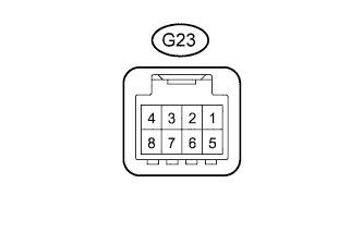
Disconnect the G23 integration control and panel assembly connector.
-
Measure the resistance and voltage according to the value(s) in the table below.
Terminal No. (Symbol) Wiring Color Terminal Description Condition Specified Condition G23-4 (GND) - Body ground W-B - Body ground Ground Always Below 1 Ω G23-5 (IG) - Body ground L - Body ground IG power supply Ignition switch ON 11 to 14 V If the result is not as specified, there may be a malfunction on the wire harness side.
-
-
CHECK AIR CONDITIONING CONTROL ASSEMBLY (w/ Rear Air Conditioning System)
-
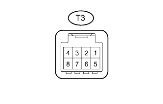
Disconnect the T3 air conditioning control assembly connector.
-
Measure the resistance and voltage according to the value(s) in the table below.
Terminal No. (Symbol) Wiring Color Terminal Description Condition Specified Condition T3-8 (E) - Body ground W-B - Body ground Ground Always Below 1 Ω T3-5 (IG) - Body ground L - Body ground IG power supply Ignition switch ON 11 to 14 V If the result is not as specified, there may be a malfunction on the wire harness side.
-
-
CHECK RAIN SENSOR (w/ Rain Sensor)
-
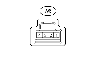
Disconnect the W6 rain sensor connector.
-
Measure the resistance and voltage according to the value(s) in the table below.
Terminal No. (Symbol) Wiring Color Terminal Description Condition Specified Condition W6-1 (ES) - Body ground W-B - Body ground Ground Always Below 1 Ω W6-4 (SIG) - Body ground GR - Body ground IG power supply Ignition switch ON 11 to 14 V If the result is not as specified, there may be a malfunction on the wire harness side.
-
-
CHECK WINDSHIELD WIPER RELAY ASSEMBLY (w/ Rain Sensor)
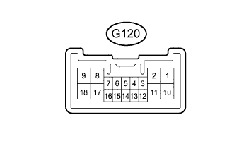
-
Disconnect the G120 windshield wiper relay assembly connector.
-
Measure the resistance and voltage according to the value(s) in the table below.
for LHD Terminal No. (Symbol) Wiring Color Terminal Description Condition Specified Condition G120-1 (EW) - Body ground W-B - Body ground Ground Always Below 1 Ω G120-17 (+B) - Body ground G - Body ground Battery power supply Always 11 to 14 V G120-3 (WIG) - Body ground G - Body ground IG power supply Ignition switch ON 11 to 14 V for RHD (for RH Side Type Wiper Switch) Terminal No. (Symbol) Wiring Color Terminal Description Condition Specified Condition G120-9 (EW) - Body ground W-B - Body ground Ground Always Below 1 Ω G120-11 (+B) - Body ground G - Body ground Battery power supply Always 11 to 14 V G120-7 (WIG) - Body ground G - Body ground IG power supply Ignition switch ON 11 to 14 V for RHD (for LH Side Type Wiper Switch) Terminal No. (Symbol) Wiring Color Terminal Description Condition Specified Condition G120-1 (EW) - Body ground W-B - Body ground Ground Always Below 1 Ω G120-17 (+B) - Body ground G - Body ground Battery power supply Always 11 to 14 V G120-3 (WIG) - Body ground G - Body ground IG power supply Ignition switch ON 11 to 14 V If the result is not as specified, there may be a malfunction on the wire harness side.
-
-
CHECK DOUBLE LOCK DOOR CONTROL RELAY ASSEMBLY (w/ Double Locking System)
-
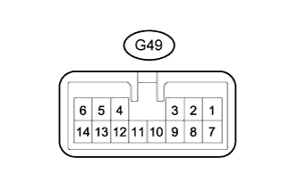
Disconnect the G49 double lock door control relay assembly connector.
-
Measure the resistance and voltage according to the value(s) in the table below.
Terminal No. (Symbol) Wiring Color Terminal Description Condition Specified Condition G49-14 (GND) - Body ground W-B - Body ground Ground Always Below 1 Ω G49-7 (CPUB) - Body ground P - Body ground Battery power supply Always 11 to 14 V G49-1 (+B) - Body ground R - Body ground Battery power supply Always 11 to 14 V If the result is not as specified, there may be a malfunction on the wire harness side.
-
-
CHECK DRIVING SUPPORT SWITCH CONTROL ECU (w/ Multi-function Switch)
-
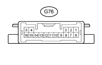
Disconnect the G76 driving support switch control ECU connector.
-
Measure the resistance and voltage according to the value(s) in the table below.
Terminal No. (Symbol) Wiring Color Terminal Description Condition Specified Condition G76-16 (GND) - Body ground W-B - Body ground Ground Always Below 1 Ω G76-6 (+B) - Body ground L - Body ground Battery power supply Always 11 to 14 V G76-7 (IG) - Body ground L - Body ground IG power supply Ignition switch ON 11 to 14 V If the result is not as specified, there may be a malfunction on the wire harness side.
-
-
CHECK COMBINATION METER ASSEMBLY
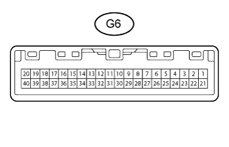
-
Disconnect the G6 combination meter assembly connector.
-
Measure the resistance and voltage according to the value(s) in the table below.
Terminal No. (Symbol) Wiring Color Terminal Description Condition Specified Condition G6-1 (EP) - Body ground W-B - Body ground Ground Always Below 1 Ω G6-26 (B) - Body ground L - Body ground Battery power supply Always 11 to 14 V G6-28 (IG+) - Body ground R - Body ground IG power supply Ignition switch ON 11 to 14 V If the result is not as specified, there may be a malfunction on the wire harness side.
-
-
CHECK ACCESSORY METER ASSEMBLY (w/ Accessory Meter)
-
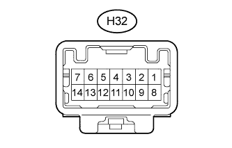
Disconnect the H32 accessory meter assembly connector.
-
Measure the resistance and voltage according to the value(s) in the table below.
Terminal No. (Symbol) Wiring Color Terminal Description Condition Specified Condition H32-8 (GND) - Body ground BR - Body ground Ground Always Below 1 Ω H32-11 (IG) - Body ground L - Body ground IG power supply Ignition switch ON 11 to 14 V H32-12 (+B) - Body ground L - Body ground Battery power supply Always 11 to 14 V If the result is not as specified, there may be a malfunction on the wire harness side.
-