MAIN BODY ECU INSTALLATION

Tech Tips
-
A bolt without a torque specification is shown in the standard bolt chart Click here.
-
Use the same procedure for RHD and LHD vehicles.
-
The procedure listed below is for LHD vehicles.
-
INSTALL MULTIPLEX NETWORK BODY ECU
Note
-
Make sure that no foreign objects contact the connecting surfaces.
-
Do not touch the ECU connector.
-
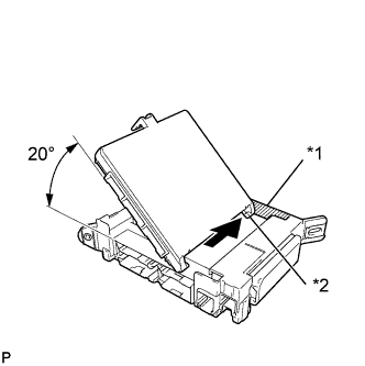
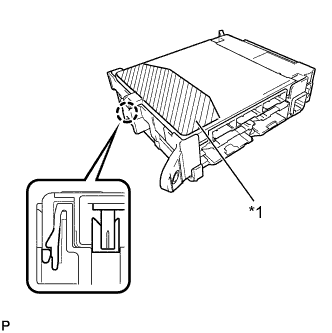
Text in Illustration *1 Housing Sidewall *2 Guide Part Insert the multiplex network body ECU until it contacts the housing sidewall of the guide part as shown in the illustration.
Tech Tips
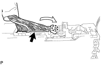
Be sure to maintain an angle of 20° or more as shown in the illustration.
-
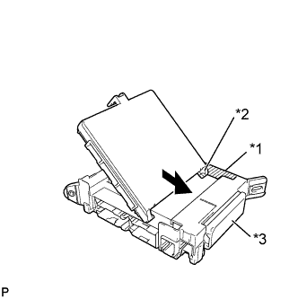
Text in Illustration *1 Housing Sidewall *2 Guide Part *3 Junction Block Fuse Slide the guide of the multiplex network body ECU along the housing sidewall toward the junction block fuses as shown in the illustration.
-
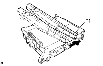
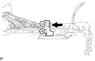
Text in Illustration *1 Side A Slide the multiplex network body ECU so that it contacts side A as shown in the illustration.
Note
Do not apply excessive force to the multiplex network body ECU.
-
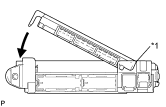
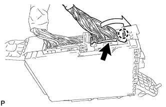
Text in Illustration *1 Side A Contact Portion With the multiplex network body ECU to side A of the junction block (point of rotation), rotate it downward as shown in the illustration.
-
Text in Illustration *1 Pushing Area Press the pushing area until the claw attaches to install the multiplex network body ECU.
Note
-
Make sure to press only the pushing area.
-
Confirm the engagement of the multiplex network body ECU and junction block by listening for a lock sound.
-
Do not apply excessive force to the multiplex network body ECU.
Tech Tips
If a lock sound cannot be heard, visually check the engagement of the lock part. The engagement can also be confirmed if the multiplex network body ECU and junction block are flush.
-
-
-
INSTALL DRIVER SIDE JUNCTION BLOCK ASSEMBLY
-
Attach the claw to install the connector as shown in the illustration.
Note
Be sure to connect each connector securely.
-
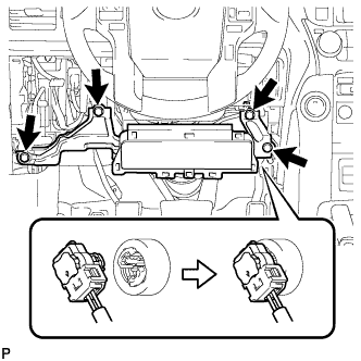
Attach the 2 claws to lock the connector lock as shown in the illustration.
-
Attach the claw to connect the connector as shown in the illustration.
Note
Be sure to connect the connector securely.
-
Install the driver side junction block assembly with the bolt and 2 nuts.
- Torque:
- 8.0 N*m { 82 kgf*cm, 71 in.*lbf }
-
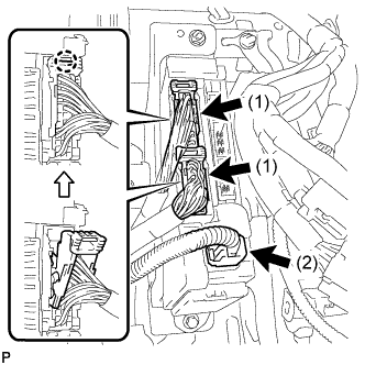
Connect the connector labeled (1).
Note
Be sure to connect each connector securely.
-
Attach the 2 claws to connect the 2 connectors labeled (2) as shown in the illustration.
Note
Be sure to connect each connector securely.
-
Connect the 3 connectors.
Note
Be sure to connect each connector securely.
-
-
INSTALL LOWER NO. 1 INSTRUMENT PANEL AIRBAG ASSEMBLY (w/ Knee Airbag)
-
Connect the connector.
Note
When handling the airbag connector, take care not to damage the airbag wire harness.
-
Install the airbag assembly with the 4 bolts.
- Torque:
- 10 N*m { 102 kgf*cm, 7 ft.*lbf }
-
-
INSTALL LOWER INSTRUMENT PANEL FINISH PANEL SUB-ASSEMBLY
-
Connect each connector and each cable.
-
w/o Knee Airbag:
-
Attach the 7 clips to install the lower instrument panel finish panel.
-
-
w/ Knee Airbag:
-
Attach the 14 clips to install the lower instrument panel finish panel.
-
-
Install the 2 bolts <C>.
-
Attach the 2 claws to close the cover.
-
-
INSTALL LOWER INSTRUMENT PANEL FINISH PANEL ASSEMBLY
-
Connect each connector.
-
Attach the 4 clips to install the instrument panel finish panel.
-
-
INSTALL INSTRUMENT PANEL FINISH PLATE GARNISH (for RHD)
-
Connect each connector.
-
Attach the 4 clips to install the instrument panel finish plate garnish.
-
-
INSTALL INSTRUMENT CLUSTER FINISH PANEL ORNAMENT (for LHD)
-
Attach the 3 clips to install the instrument cluster finish panel ornament.
-
-
INSTALL INSTRUMENT SIDE PANEL LH
-
Attach the 5 clips, claw and 3 guides to install the instrument side panel.
-
-
INSTALL NO. 1 INSTRUMENT PANEL UNDER COVER SUB-ASSEMBLY
-
for LHD:
-
Attach the 2 clips and 2 guides to install the No. 1 instrument panel under cover.
-
Install the screw.
-
-
for RHD:
-
Attach the 3 clips and 2 guides to install the No. 1 instrument panel under cover.
-
Install the screw.
-
-
-
INSTALL COWL SIDE TRIM BOARD LH
-
for 5 Door:
Install the cowl side trim board LH Click here.
-
for 3 Door:
Install the cowl side trim board LH Click here.
-
-
INSTALL DOOR SCUFF PLATE ASSEMBLY LH
-
for 5 Door:
Install the door scuff plate assembly LH Click here.
-
for 3 Door:
Install the door scuff plate assembly LH Click here.
-
-
CONNECT CABLE TO NEGATIVE BATTERY TERMINAL
Note
When disconnecting the cable, some systems need to be initialized after the cable is reconnected Click here.
-
CHECK SRS WARNING LIGHT
-
Check the SRS warning light Click here.
-