CLEARANCE WARNING BUZZER INSTALLATION

-
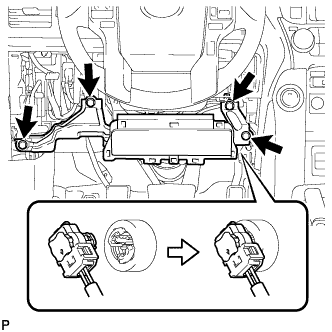
INSTALL NO. 1 CLEARANCE WARNING BUZZER
-
Attach the clamp to install the No. 1 clearance warning buzzer.
-
Connect the connector.
-
-
INSTALL RADIO RECEIVER ASSEMBLY (w/ Audio)
-
for Upper Side:
Install the radio receiver assembly Click here.
-
for Lower Side:
Install the radio receiver assembly Click here.
-
-
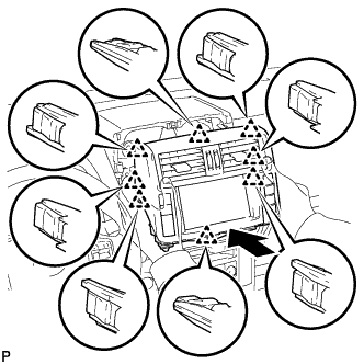
INSTALL ACCESSORY METER ASSEMBLY (w/ Display, w/o Navigation System)
-
Connect the connectors.
-
Insert the accessory meter and attach the 10 clips on its backside.
-
Install the accessory meter with the 2 bolts.
- Torque:
- 12 N*m { 122 kgf*cm, 9 ft.*lbf }
-
-
INSTALL DISPLAY AND NAVIGATION MODULE DISPLAY (w/ Display, w/ Navigation System)
-
Connect the connectors.
-
Insert the display and navigation module display and attach the 8 clips on the backside of the display and navigation module display.
Note
When inserting the display, do not press the knobs on it.
-
Install the display and navigation module display with the 4 bolts.
- Torque:
- 12.5 N*m { 127 kgf*cm, 9 ft.*lbf }
-
-
INSTALL RADIO TUNER OPENING COVER (w/o Audio)
-
Install the radio tuner opening cover with the 4 bolts.
-
-
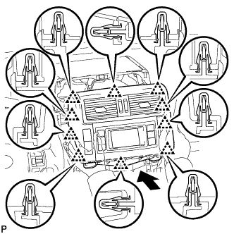
INSTALL CENTER INSTRUMENT CLUSTER FINISH PANEL ASSEMBLY (w/o Display)
-
Attach the 10 clips to install the center instrument cluster finish panel.
-
-
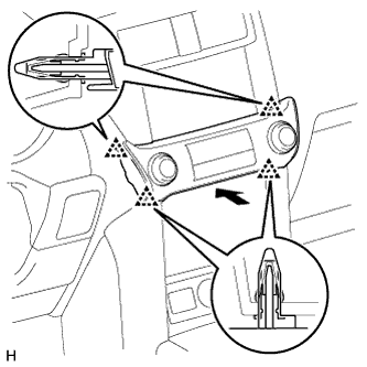
INSTALL INTEGRATION CONTROL AND PANEL ASSEMBLY
-
Connect the connector.
-
Attach the 4 clips to install the integration control and panel assembly.
-
-
INSTALL LOWER NO. 1 INSTRUMENT PANEL AIRBAG ASSEMBLY
-
Connect the connector.
Note
When handling the airbag connector, take care not to damage the airbag wire harness.
-
Install the airbag assembly with the 4 bolts.
- Torque:
- 10 N*m { 102 kgf*cm, 7 ft.*lbf }
-
-
INSTALL LOWER INSTRUMENT PANEL FINISH PANEL SUB-ASSEMBLY
-
Connect each connector.
-
Attach the 4 clips to install the instrument panel finish panel.
-
-
INSTALL LOWER INSTRUMENT PANEL FINISH PANEL ASSEMBLY
-
Connect each connector and each cable.
-
Attach the 14 clips to install the lower instrument panel finish panel.
-
Install the 2 bolts.
-
Attach the 2 claws to close the cover.
-
-
INSTALL NO. 1 INSTRUMENT PANEL UNDER COVER SUB-ASSEMBLY (for LHD)
-
for LHD:
-
Attach the 2 clips and 2 guides to install the No. 1 instrument panel under cover.
-
Install the screw.
-
-
for RHD:
-
Attach the 3 clips and 2 guides to install the No. 1 instrument panel under cover.
-
Install the screw.
-
-
-
INSTALL INSTRUMENT CLUSTER FINISH PANEL ORNAMENT (for LHD)
-
Attach the 3 clips to install the instrument cluster finish panel ornament.
-
-
INSTALL INSTRUMENT SIDE PANEL LH (for LHD)
-
Attach the 5 clips, claw and 3 guides to install the instrument side panel.
-
-
INSTALL COWL SIDE TRIM BOARD LH (for LHD)
-
Attach the clip and claw to install the cowl side trim board.
-
Install the clip.
-
-
INSTALL DOOR SCUFF PLATE ASSEMBLY LH (for LHD)
-
Attach the 4 clips, 10 claws and 2 guides to install the door scuff plate.
-
-
INSTALL NO. 2 INSTRUMENT PANEL UNDER COVER SUB-ASSEMBLY (for RHD)
-
Attach the 3 clips and 2 guides to install the No. 2 instrument panel under cover.
-
Install the screw.
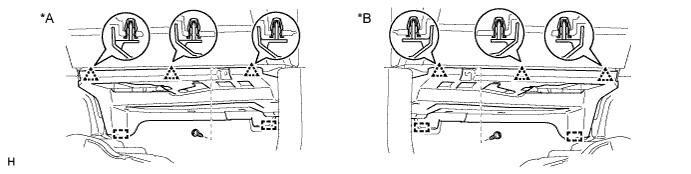
Text in Illustration *A for LHD *B for RHD
-
-
INSTALL INSTRUMENT SIDE PANEL RH (for RHD)
-
Attach the 5 clips, claw and 3 guides to install the instrument side panel.
-
-
INSTALL COWL SIDE TRIM BOARD RH (for RHD)
-
Attach the clip and claw to install the cowl side trim board.
-
Install the clip.
-
-
INSTALL DOOR SCUFF PLATE ASSEMBLY RH (for RHD)
-
Attach the 4 clips, 10 claws and 2 guides to install the door scuff plate.
-
-
INSTALL INSTRUMENT PANEL FINISH PLATE GARNISH (for RHD)
-
Connect each connector.
-
Attach the 4 clips to install the instrument panel finish plate garnish.
-
-
CONNECT CABLE TO NEGATIVE BATTERY TERMINAL
Note
When disconnecting the cable, some systems need to be initialized after the cable is reconnected Click here.
-
CHECK SRS WARNING LIGHT
-
Check the SRS warning light Click here.
-