REAR VIEW MONITOR SYSTEM (w/o Side Monitor System) Image from Camera for Rear View Monitor is Abnormal
DESCRIPTION
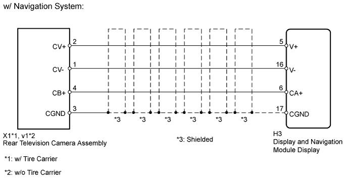
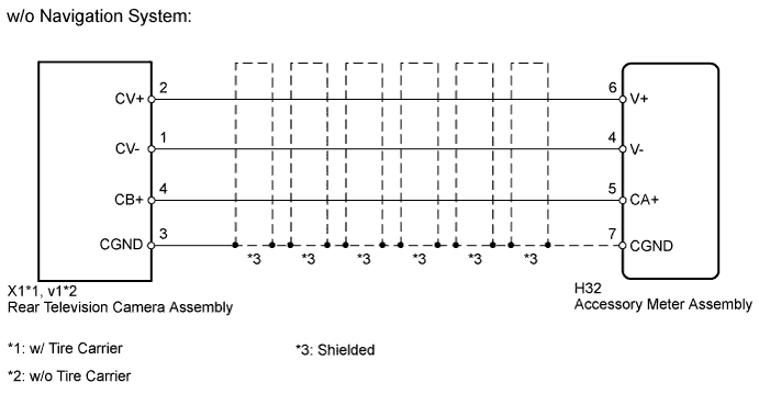
This is the display signal circuit of the rear television camera assembly.
WIRING DIAGRAM
INSPECTION PROCEDURE
PROCEDURE
-
CHECK NAVIGATION SYSTEM
-
Check the navigation system.
Result Result Proceed to w/ Navigation System A w/o Navigation System B
B 
CHECK HARNESS AND CONNECTOR (ACCESSORY METER - REAR TELEVISION CAMERA) Click here
A 
-
-
CHECK HARNESS AND CONNECTOR (DISPLAY AND NAVIGATION MODULE DISPLAY - REAR TELEVISION CAMERA)
-
Disconnect the H3 display and navigation module display connector.
-
Disconnect the X1*1 or v1*2 rear television camera assembly connector.
-
*1: w/ Tire Carrier
-
*2: w/o Tire Carrier
-
-
Measure the resistance according to the value(s) in the table below.
Standard Resistance w/ Tire Carrier Tester Connection Condition Specified Condition H3-5 (V+) - X1-2 (CV+) Always Below 1 Ω H3-6 (CA+) - X1-4 (CB+) Always Below 1 Ω H3-16 (V-) - X1-1 (CV-) Always Below 1 Ω H3-17 (CGND) - X1-3 (CGND) Always Below 1 Ω H3-5 (V+) - Body ground Always 10 kΩ or higher H3-6 (CA+) - Body ground Always 10 kΩ or higher H3-16 (V-) - Body ground Always 10 kΩ or higher H3-17 (CGND) - Body ground Always 10 kΩ or higher w/o Tire Carrier Tester Connection Condition Specified Condition H3-5 (V+) - v1-2 (CV+) Always Below 1 Ω H3-6 (CA+) - v1-4 (CB+) Always Below 1 Ω H3-16 (V-) - v1-1 (CV-) Always Below 1 Ω H3-17 (CGND) - v1-3 (CGND) Always Below 1 Ω H3-5 (V+) - Body ground Always 10 kΩ or higher H3-6 (CA+) - Body ground Always 10 kΩ or higher H3-16 (V-) - Body ground Always 10 kΩ or higher H3-17 (CGND) - Body ground Always 10 kΩ or higher
NG 
REPAIR OR REPLACE HARNESS OR CONNECTOR
OK
-
-
CHECK DISPLAY AND NAVIGATION MODULE DISPLAY
-
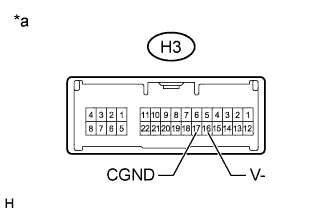
Text in Illustration *a Component without harness connected
(Display and Navigation Module Display)
Disconnect the H3 display and navigation module display connector.
-
Measure the resistance according to the value(s) in the table below.
Standard Resistance Tester Connection Condition Specified Condition H3-16 (V-) - Body ground Always Below 1 Ω H3-17 (CGND) - Body ground Always Below 1 Ω
NG
REPLACE DISPLAY AND NAVIGATION MODULE DISPLAY Click here
OK
-
-
CHECK DISPLAY AND NAVIGATION MODULE DISPLAY
-
Disconnect the X1*1 or v1*2 rear television camera assembly connector.
-
*1: w/ Tire Carrier
-
*2: w/o Tire Carrier
-
-
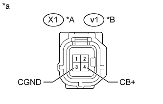
Text in Illustration *A w/ Tire Carrier *B w/o Tire Carrier *a Front view of wire harness connector
(to Rear Television Camera Assembly)
Measure the voltage according to the value(s) in the table below.
Standard Voltage w/ Tire Carrier Tester Connection Condition Specified Condition X1-4 (CB+) - X1-3 (CGND) Ignition switch ON, shift lever in R 5.5 to 7.05 V w/o Tire Carrier Tester Connection Condition Specified Condition v1-4 (CB+) - v1-3 (CGND) Ignition switch ON, shift lever in R 5.5 to 7.05 V
NG
REPLACE DISPLAY AND NAVIGATION MODULE DISPLAY Click here
OK
-
-
CHECK REAR TELEVISION CAMERA ASSEMBLY
-
Using an oscilloscope, check the waveform.
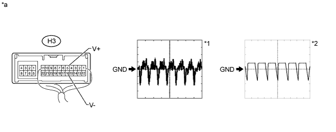
Text in Illustration *a Component with harness connected
(Display and Navigation Module Display)
- - Measurement Condition Item Content Tester Connection H3-5 (V+) - H3-16 (V-) Tool Setting 0.2 V/DIV., 50 μs/DIV. Condition
-
Ignition switch ON, shift lever in R*1
-
Ignition switch ON, shift lever in R, screen blacked out by covering camera lens*2
OK Waveform is as shown in illustration. Result Result Proceed to OK A NG (w/ Tire Carrier) B NG (w/o Tire Carrier) C -
B
REPLACE REAR TELEVISION CAMERA ASSEMBLY Click here
C
REPLACE REAR TELEVISION CAMERA ASSEMBLY Click here
A 
PROCEED TO NEXT SUSPECTED AREA SHOWN IN PROBLEM SYMPTOMS TABLE Click here
-
-
CHECK HARNESS AND CONNECTOR (ACCESSORY METER - REAR TELEVISION CAMERA)
-
Disconnect the H32 accessory meter assembly connector.
-
Disconnect the X1*1 or v1*2 rear television camera assembly connector.
-
*1: w/ Tire Carrier
-
*2: w/o Tire Carrier
-
-
Measure the resistance according to the value(s) in the table below.
Standard Resistance w/ Tire Carrier Tester Connection Condition Specified Condition H32-6 (V+) - X1-2 (CV+) Always Below 1 Ω H32-5 (CA+) - X1-4 (CB+) Always Below 1 Ω H32-4 (V-) - X1-1 (CV-) Always Below 1 Ω H32-7 (CGND) - X1-3 (CGND) Always Below 1 Ω H32-6 (V+) - Body ground Always 10 kΩ or higher H32-5 (CA+) - Body ground Always 10 kΩ or higher H32-4 (V-) - Body ground Always 10 kΩ or higher H32-7 (CGND) - Body ground Always 10 kΩ or higher w/o Tire Carrier Tester Connection Condition Specified Condition H32-6 (V+) - v1-2 (CV+) Always Below 1 Ω H32-5 (CA+) - v1-4 (CB+) Always Below 1 Ω H32-4 (V-) - v1-1 (CV-) Always Below 1 Ω H32-7 (CGND) - v1-3 (CGND) Always Below 1 Ω H32-6 (V+) - Body ground Always 10 kΩ or higher H32-5 (CA+) - Body ground Always 10 kΩ or higher H32-4 (V-) - Body ground Always 10 kΩ or higher H32-7 (CGND) - Body ground Always 10 kΩ or higher
NG
REPAIR OR REPLACE HARNESS OR CONNECTOR
OK
-
-
CHECK ACCESSORY METER ASSEMBLY
-
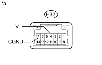
Text in Illustration *a Component without harness connected
(Accessory Meter Assembly)
Disconnect the H32 accessory meter assembly connector.
-
Measure the resistance according to the value(s) in the table below.
Standard Resistance Tester Connection Condition Specified Condition H32-4 (V-) - Body ground Always Below 1 Ω H32-7 (CGND) - Body ground Always Below 1 Ω
NG
REPLACE ACCESSORY METER ASSEMBLY Click here
OK
-
-
CHECK ACCESSORY METER ASSEMBLY
-
Text in Illustration *A w/ Tire Carrier *B w/o Tire Carrier *a Front view of wire harness connector
(to Rear Television Camera Assembly)
Disconnect the X1*1 or v1*2 rear television camera assembly connector.
-
*1: w/ Tire Carrier
-
*2: w/o Tire Carrier
-
-
Measure the voltage according to the value(s) in the table below.
Standard Voltage w/ Tire Carrier Tester Connection Condition Specified Condition X1-4 (CB+) - X1-3 (CGND) Ignition switch ON, shift lever in R 5.5 to 7.05 V w/o Tire Carrier Tester Connection Condition Specified Condition v1-4 (CB+) - v1-3 (CGND) Ignition switch ON, shift lever in R 5.5 to 7.05 V
NG
REPLACE ACCESSORY METER ASSEMBLY Click here
OK
-
-
CHECK REAR TELEVISION CAMERA ASSEMBLY
-
Using an oscilloscope, check the waveform.
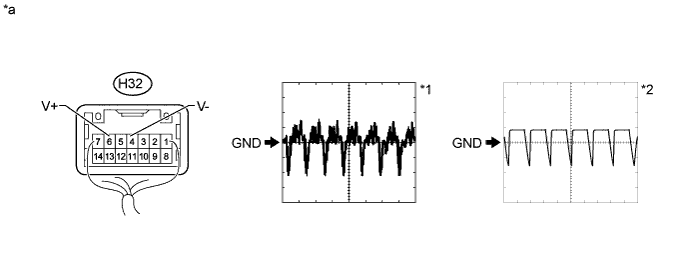
Text in Illustration *a Component with harness connected
(Accessory Meter Assembly)
- - Measurement Condition Item Content Tester Connection H32-6 (V+) - H32-4 (V-) Tool Setting 0.2 V/DIV., 50 μs/DIV. Condition
-
Ignition switch ON, shift lever in R*1
-
Ignition switch ON, shift lever in R, screen blacked out by covering camera lens*2
OK Waveform is as shown in illustration. Result Result Proceed to OK A NG (w/ Tire Carrier) B NG (w/o Tire Carrier) C -
B
REPLACE REAR TELEVISION CAMERA ASSEMBLY Click here
C
REPLACE REAR TELEVISION CAMERA ASSEMBLY Click here
A
PROCEED TO NEXT SUSPECTED AREA SHOWN IN PROBLEM SYMPTOMS TABLE Click here
-