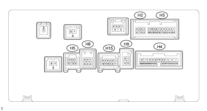
REAR VIEW MONITOR SYSTEM (w/o Side Monitor System) TERMINALS OF ECU

-
*1: w/ Navigation system
-
*2: w/o Navigation system
-
CHECK DISPLAY AND NAVIGATION MODULE DISPLAY (for DVD)*1
-
Measure the voltage, resistance and check for pulses according to value(s) in the table below.
Terminal No. (Symbol) Wiring Color Terminal Description Condition Specified Condition H3-6 (CA+) - H3-17 (CGND) B - Shielded Power source Ignition switch ON, shift lever in R 5.5 to 7.05 V H3-5 (V+) - H3-16 (V-) R - W Display signal Ignition switch ON, shift lever in R Pulse generation
(See waveform 1)
Ignition switch ON, shift lever in R, screen blacked out by covering camera lens Pulse generation
(See waveform 2)
H3-17 (CGND) - Body ground Shielded - Body ground Shielding Always Below 1 V H4-1 (+B1) - H4-10 (GND) SB - BR Battery Always 11 to 14 V H4-10 (GND) - Body ground BR - Body ground Ground Always Below 1 Ω H4-16 (REV) - H4-10 (GND) R - BR Reverse signal Ignition switch ON, shift lever in R 11 to 14 V Ignition switch ON, shift lever not in R Below 1 V -
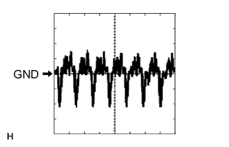
Using an oscilloscope, check waveform 1.
Measurement Condition Item Content Terminal No. (Symbol) H3-5 (V+) - H3-16 (V-) Tool Setting 0.2 V/DIV., 50 μs/DIV. Condition Ignition switch ON, shift lever in R -
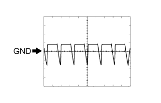
Using an oscilloscope, check waveform 2.
Measurement Condition Item Content Terminal No. (Symbol) H3-5 (V+) - H3-16 (V-) Tool Setting 0.2 V/DIV., 50 μs/DIV. Condition Ignition switch ON, shift lever in R, screen blacked out by covering camera lens
-
-
CHECK ACCESSORY METER ASSEMBLY*2

-
Measure the voltage, resistance and check for pulses according to value(s) in the table below.
Terminal No. (Symbol) Wiring Color Terminal Description Condition Specified Condition H32-8 (GND) - Body ground BR - Body ground Ground Always Below 1 Ω H32-12 (+B) - H32-8 (GND) L - BR Battery Always 11 to 14 V H32-5 (CA+) - H32-7 (CGND) B - Shielded Power source to rear television camera Ignition switch ON, shift lever in R 5.5 to 7.05 V H32-7 (CGND) - Body ground Shielded - Body ground Rear television camera shielded ground Always Below 1 V H32-13 (REV) - H32-8 (GND) R - BR Reverse signal Ignition switch ON, shift lever in R 11 to 14 V Ignition switch ON, shift lever not in R Below 1 V H32-11 (IG) - H32-8 (GND) L - BR Power Source (IG) Ignition switch ON 11 to 14 V H32-6 (V+) - H32-4 (V-) R - W Display signal Ignition switch ON, shift lever in R Pulse generation
(See waveform 1)
Ignition switch ON, shift lever in R, screen blacked out by covering camera lens Pulse generation
(See waveform 2)
-
Using an oscilloscope, check waveform 1.
Measurement Condition Item Content Terminal No. (Symbol) H32-6 (V+) - H32-4 (V-) Tool Setting 0.2 V/DIV., 50 μs/DIV. Condition Ignition switch ON, shift lever in R -
Using an oscilloscope, check waveform 2.
Measurement Condition Item Content Terminal No. (Symbol) H32-6 (V+) - H32-4 (V-) Tool Setting 0.2 V/DIV., 50 μs/DIV. Condition Ignition switch ON, shift lever in R, screen blacked out by covering camera lens
-