REAR VIEW MONITOR SYSTEM (w/ Side Monitor System) ECU Power Source Circuit
DESCRIPTION
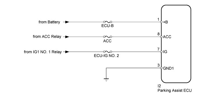
This circuit is the power source circuit used to operate the parking assist ECU. The parking assist ECU controls the rear view monitor system, wide view front monitor system, side monitor system and TOYOTA parking assist-sensor system. When a malfunction occurs in this circuit, each system will be abnormal.
Tech Tips
-
The parking assist ECU is connected to other ECUs via CAN communication or AVC-LAN communication.
-
If the parking assist ECU does not operate due to a power source problem, other system DTCs may be stored due to a CAN communication interruption.
WIRING DIAGRAM
INSPECTION PROCEDURE
Note
Inspect the fuses for circuits related to this system before performing the following inspection procedure.
PROCEDURE
-
CHECK HARNESS AND CONNECTOR (PARKING ASSIST ECU - BATTERY AND BODY GROUND)
-
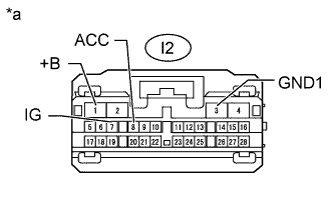
Text in Illustration *a Front view of wire harness connector
(to Parking Assist ECU)
Disconnect the I2 parking assist ECU connector.
-
Measure the resistance according to the value(s) in the table below.
Standard Resistance Tester Connection Condition Specified Condition I2-3 (GND) - Body ground Always Below 1 Ω -
Measure the voltage according to the value(s) in the table below.
Standard Voltage Tester Connection Switch Condition Specified Condition I2-1 (+B) - Body ground Always 11 to 14 V I2-7 (IG) - Body ground Ignition switch ON 11 to 14 V Ignition switch off Below 1 V I2-8 (ACC) - Body ground Ignition switch ACC 11 to 14 V Ignition switch off Below 1 V
NG 
REPAIR OR REPLACE HARNESS OR CONNECTOR
OK 
PROCEED TO NEXT SUSPECTED AREA SHOWN IN PROBLEM SYMPTOMS TABLE Click here
-