REAR VIEW MONITOR SYSTEM (w/ Side Monitor System) Image from Camera for Rear View Monitor is Abnormal
DESCRIPTION
The display signal of the rear television camera assembly is transmitted to the parking assist ECU.
WIRING DIAGRAM
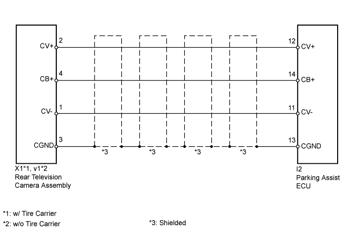
INSPECTION PROCEDURE
PROCEDURE
-
CHECK HARNESS AND CONNECTOR (PARKING ASSIST ECU - REAR TELEVISION CAMERA)
-
w/ Tire Carrier:
-
Disconnect the I2 parking assist ECU connector.
-
Disconnect the X1 rear television camera assembly connector.
-
Measure the resistance according to the value(s) in the table below.
Standard Resistance Tester Connection Condition Specified Condition I2-11 (CV-) - X1-1 (CV-) Always Below 1 Ω I2-12 (CV+) - X1-2 (CV+) Always Below 1 Ω I2-13 (CGND) - X1-3 (CGND) Always Below 1 Ω I2-14 (CB+) - X1-4 (CB+) Always Below 1 Ω I2-11 (CV-) - Body ground Always 10 kΩ or higher I2-12 (CV+) - Body ground Always 10 kΩ or higher I2-13 (CGND) - Body ground Always 10 kΩ or higher I2-14 (CB+) - Body ground Always 10 kΩ or higher
-
-
w/o Tire Carrier:
-
Disconnect the I2 parking assist ECU connector.
-
Disconnect the v1 rear television camera assembly connector.
-
Measure the resistance according to the value(s) in the table below.
Standard Resistance Tester Connection Condition Specified Condition I2-11 (CV-) - v1-1 (CV-) Always Below 1 Ω I2-12 (CV+) - v1-2 (CV+) Always Below 1 Ω I2-13 (CGND) - v1-3 (CGND) Always Below 1 Ω I2-14 (CB+) - v1-4 (CB+) Always Below 1 Ω I2-11 (CV-) - Body ground Always 10 kΩ or higher I2-12 (CV+) - Body ground Always 10 kΩ or higher I2-13 (CGND) - Body ground Always 10 kΩ or higher I2-14 (CB+) - Body ground Always 10 kΩ or higher
-
NG 
REPAIR OR REPLACE HARNESS OR CONNECTOR
OK 
-
-
CHECK PARKING ASSIST ECU
-
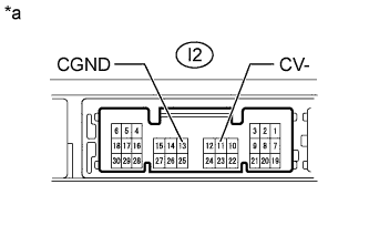
Text in Illustration *a Component without harness connected
(Parking Assist ECU)
Disconnect the I2 parking assist ECU connector.
-
Measure the resistance according to the value(s) in the table below.
Standard Resistance Tester Connection Condition Specified Condition I2-11 (CV-) - Body ground Always Below 1 Ω I2-13 (CGND) - Body ground Always Below 1 Ω Result Result Proceed to OK A NG (for LHD) B NG (for RHD) C
B
REPLACE PARKING ASSIST ECU Click here
C
REPLACE PARKING ASSIST ECU Click here
A
-
-
CHECK PARKING ASSIST ECU
-
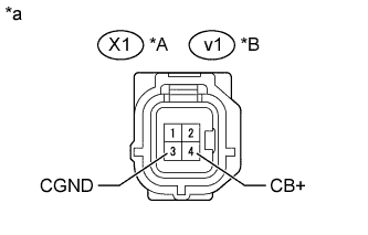
Text in Illustration *A w/ Tire Carrier *B w/o Tire Carrier *a Front view of wire harness connector:
(to Rear Television Camera Assembly)
Disconnect the X1*1 or v1*2 rear television camera assembly connector.
-
Measure the voltage according to the value(s) in the table below.
Standard Voltage w/ Tire Carrier Tester Connection Condition Specified Condition X1-4 (CB+) - X1-3 (CGND) Ignition switch ON, shift lever in R 5.5 to 7.05 V w/o Tire Carrier Tester Connection Condition Specified Condition v1-4 (CB+) - v1-3 (CGND) Ignition switch ON, shift lever in R 5.5 to 7.05 V Result Result Proceed to OK A NG (for LHD) B NG (for RHD) C
B
REPLACE PARKING ASSIST ECU Click here
C
REPLACE PARKING ASSIST ECU Click here
A
-
-
CHECK REAR TELEVISION CAMERA ASSEMBLY
-
Using an oscilloscope, check the waveform.
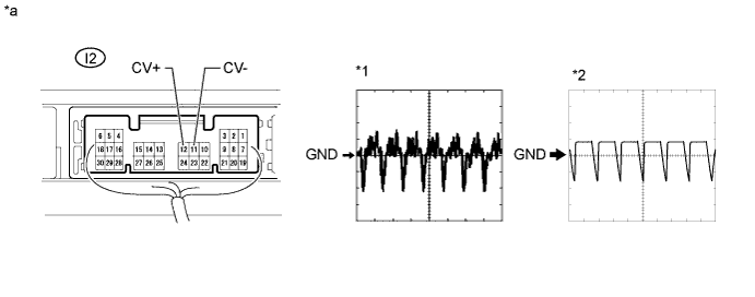
Text in Illustration *a Component with harness connected
(Parking Assist ECU)
- - Measurement Condition Item Content Tester Connection I2-12(CV+) - I2-11 (CV-) Tool Setting 0.2 V/DIV., 50 μs/DIV. Condition
-
Ignition switch ON, shift lever in R*1
-
Ignition switch ON, shift lever in R, screen blacked out by covering camera lens*2
OK Waveform is as shown in illustration. Result Result Proceed to OK (for LHD) A OK (for RHD) B NG (w/ Tire Carrier) C NG (w/o Tire Carrier) D -
B
REPLACE PARKING ASSIST ECU Click here
C
REPLACE REAR TELEVISION CAMERA ASSEMBLY Click here
D
REPLACE REAR TELEVISION CAMERA ASSEMBLY Click here
A 
REPLACE PARKING ASSIST ECU Click here
-