REAR VIEW MONITOR SYSTEM (w/ Side Monitor System), Diagnostic DTC:C1621, C1622

| DTC Code | DTC Name |
|---|---|
| C1621 | Back Camera Power Supply Failure |
| C1622 | Open or Short Circuit in Back Camera Signal |
DESCRIPTION
This DTC is stored if the parking assist ECU judges as a result of its self check that the signals or signal lines between the parking assist ECU and the rear television camera assembly are not normal.
| DTC Code | DTC Detection Condition | Trouble Area |
|---|---|---|
| C1621 | Rear television camera power supply failure |
|
| C1622 | Open or Short Circuit in rear television camera signal |
|
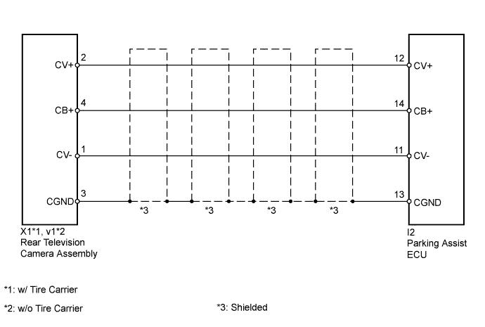
WIRING DIAGRAM
INSPECTION PROCEDURE
PROCEDURE
-
CHECK FOR DTC
-
Clear the DTCs Click here.
-
Check for DTCs Click here.
Result Result Proceed to No DTC is output A DTC is output B
B 
CHECK HARNESS AND CONNECTOR (PARKING ASSIST ECU - REAR TELEVISION CAMERA) Click here
A 
USE SIMULATION METHOD TO CHECK Click here
-
-
CHECK HARNESS AND CONNECTOR (PARKING ASSIST ECU - REAR TELEVISION CAMERA)
-
w/ Tire Carrier:
-
Disconnect the I2 parking assist ECU connector.
-
Disconnect the X1 rear television camera assembly connector.
-
Measure the resistance according to the value(s) in the table below.
Standard Resistance Tester Connection Condition Specified Condition I2-11 (CV-) - X1-1 (CV-) Always Below 1 Ω I2-12 (CV+) - X1-2 (CV+) Always Below 1 Ω I2-13 (CGND) - X1-3 (CGND) Always Below 1 Ω I2-14 (CB+) - X1-4 (CB+) Always Below 1 Ω I2-11 (CV-) - Body ground Always 10 kΩ or higher I2-12 (CV+) - Body ground Always 10 kΩ or higher I2-13 (CGND) - Body ground Always 10 kΩ or higher I2-14 (CB+) - Body ground Always 10 kΩ or higher
-
-
w/o Tire Carrier:
-
Disconnect the I2 parking assist ECU connector.
-
Disconnect the v1 rear television camera assembly connector.
-
Measure the resistance according to the value(s) in the table below.
Standard Resistance Tester Connection Condition Specified Condition I2-11 (CV-) - v1-1 (CV-) Always Below 1 Ω I2-12 (CV+) - v1-2 (CV+) Always Below 1 Ω I2-13 (CGND) - v1-3 (CGND) Always Below 1 Ω I2-14 (CB+) - v1-4 (CB+) Always Below 1 Ω I2-11 (CV-) - Body ground Always 10 kΩ or higher I2-12 (CV+) - Body ground Always 10 kΩ or higher I2-13 (CGND) - Body ground Always 10 kΩ or higher I2-14 (CB+) - Body ground Always 10 kΩ or higher
-
NG 
REPAIR OR REPLACE HARNESS OR CONNECTOR
OK 
-
-
CHECK PARKING ASSIST ECU
-
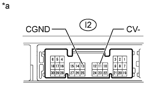
Text in Illustration *a Component without harness connected
(Parking Assist ECU)
Disconnect the I2 parking assist ECU connector.
-
Measure the resistance according to the value(s) in the table below.
Standard Resistance Tester Connection Condition Specified Condition I2-11 (CV-) - Body ground Always Below 1 Ω I2-13 (CGND) - Body ground Always Below 1 Ω Result Result Proceed to OK A NG (for LHD) B NG (for RHD) C
B
REPLACE PARKING ASSIST ECU Click here
C
REPLACE PARKING ASSIST ECU Click here
A
-
-
CHECK PARKING ASSIST ECU
-
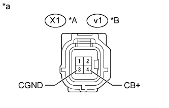
Text in Illustration *A w/ Tire Carrier *B w/o Tire Carrier *a Front view of wire harness connector:
(to Rear Television Camera Assembly)
Disconnect the X1*1 or v1*2 rear television camera assembly connector.
-
Measure the voltage according to the value(s) in the table below.
Standard Voltage w/ Tire Carrier Tester Connection Condition Specified Condition X1-4 (CB+) - X1-3 (CGND) Ignition switch ON, shift lever in R 5.5 to 7.05 V w/o Tire Carrier Tester Connection Condition Specified Condition v1-4 (CB+) - v1-3 (CGND) Ignition switch ON, shift lever in R 5.5 to 7.05 V Result Result Proceed to OK A NG (for LHD) B NG (for RHD) C
B
REPLACE PARKING ASSIST ECU Click here
C
REPLACE PARKING ASSIST ECU Click here
A
-
-
CHECK REAR TELEVISION CAMERA ASSEMBLY
-
Using an oscilloscope, check the waveform.
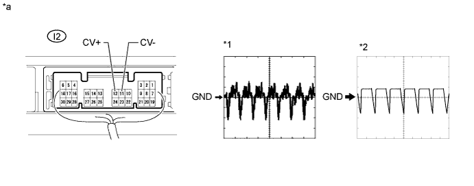
Text in Illustration *a Component with harness connected
(Parking Assist ECU)
- - Measurement Condition Item Content Tester Connection I2-12(CV+) - I2-11 (CV-) Tool Setting 0.2 V/DIV., 50 μs/DIV. Condition
-
Ignition switch ON, shift lever in R*1
-
Ignition switch ON, shift lever in R, screen blacked out by covering camera lens*2
OK Waveform is as shown in illustration. Result Result Proceed to OK (for LHD) A OK (for RHD) B NG (w/ Tire Carrier) C NG (w/o Tire Carrier) D -
B
REPLACE PARKING ASSIST ECU Click here
C
REPLACE REAR TELEVISION CAMERA ASSEMBLY Click here
D
REPLACE REAR TELEVISION CAMERA ASSEMBLY Click here
A
REPLACE PARKING ASSIST ECU Click here
-