SIDE MONITOR SYSTEM (w/ Rear View Monitor System) TERMINALS OF ECU

-
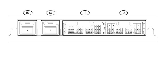
CHECK PARKING ASSIST ECU
-
Measure the voltage, resistance and check for pulses according to value(s) in the table below.
Terminal No. (Symbol) Wiring Color Terminal Description Condition Specified Condition I3-1 (+B) - I3-3 (GND1) L - W-B Power source signal Always 11 to 14 V I3-3 (GND1) - Body ground W-B - Body ground Ground Always Below 1 Ω I3-7 (IG) - I3-3 (GND1) L - W-B IG Power source signal Ignition switch ON 11 to 14 V I3-8 (ACC) - I3-3 (GND1) P - W-B ACC Power source signal Ignition switch ACC 11 to 14 V I3-23 (BLSW) - I3-3 (GND1) L - W-B Wide view front and side monitor switch signal Ignition switch ON, wide view front and side monitor switch pushed in Below 1 V Ignition switch ON, wide view front and side monitor switch not pushed in 4.0 to 5.5 V I3-24 (TX-) LG AVC-LAN communication signal - - I3-25 (TX+) L AVC-LAN communication signal - - I2-15 (SCV-) - I3-3 (GND1) W - W-B Front passenger side television camera ground Always Below 1 V I2-16 (SCV+) - I3-15 (SCV-) R - W Front passenger side television camera display signal (NTSC) input Ignition switch ON, wide view front and side monitor switch on Pulse generation
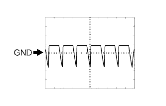
(See waveform 1)
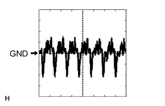
Ignition switch ON, wide view front and side monitor switch on and screen blacked out by covering camera lens Pulse generation
(See waveform 2)
I2-17 (SGND) - Body ground GR - Body ground Front passenger side television camera shield ground Always Below 1 V I2-18 (SCB+) - I3-3 (GND1) B - W-B Power source to front passenger side television camera Ignition switch ON, wide view front and side monitor switch on 5.8 to 7.05 V I2-27 (DCV-) - I3-3 (GND1)
*
W - W-B Driver side television camera ground Always Below 1 V I2-28 (DCV+) - I3-27 (DCV-)
*
R - W Driver side television camera display signal (NTSC) input Ignition switch ON, wide view front and side monitor switch on Pulse generation
(See waveform 3)
Ignition switch ON, wide view front and side monitor switch on and screen blacked out by covering camera lens Pulse generation
(See waveform 4)
I2-29 (DGND) - Body ground
*
GR - Body ground Driver side television camera shield ground Always Below 1 V I2-30 (DCB+) - I3-3 (GND1)
*
B - W-B Power source to driver side television camera Ignition switch ON, wide view front and side monitor switch on 5.8 to 7.05 V
-
*: w/ Multi-terrain Monitor
-
-
Using an oscilloscope, check waveform 1.
Measurement Condition Item Content Terminal No. (Symbol) I2-16 (SCV+) - I3-15 (SCV-) Tool Setting 200 mV/DIV., 50 μsec./DIV. Condition Ignition switch ON, wide view front and side monitor switch on -
Using an oscilloscope, check waveform 2.
Measurement Condition Item Content Terminal No. (Symbol) I2-16 (SCV+) - I3-15 (SCV-) Tool Setting 200 mV/DIV., 50 μsec./DIV. Condition Ignition switch ON, wide view front and side monitor switch on, screen blacked out by covering camera lens -
Using an oscilloscope, check waveform 3.
Measurement Condition Item Content Terminal No. (Symbol) I2-28 (DCV+) - I3-27 (DCV-) Tool Setting 200 mV/DIV., 50 μsec./DIV. Condition Ignition switch ON, wide view front and side monitor switch on -
Using an oscilloscope, check waveform 4.
Measurement Condition Item Content Terminal No. (Symbol) I2-28 (DCV+) - I3-27 (DCV-) Tool Setting 200 mV/DIV., 50 μsec./DIV. Condition Ignition switch ON, wide view front and side monitor switch on, screen blacked out by covering camera lens
-