SIDE MONITOR SYSTEM (w/ Rear View Monitor System) SYSTEM DESCRIPTION

-
*: w/ Multi-terrain monitor
-
GENERAL
-
This system has a side television camera assembly built into the front passenger side outer rear view mirror assembly and driver side outer rear view mirror assembly* to display the passenger side view and driver side view* of the vehicle on the accessory meter assembly.
-
This system consists of the following components: steering pad switch assembly (Wide view front and side monitor switch) and combination meter assembly.
-
Front passenger side television camera assembly
-
Driver side television camera assembly*
-
Parking assist ECU
-
Accessory meter assembly
-
Steering pad switch assembly (Wide view front and side monitor switch)
-
Spiral cable sub-assembly
-
Driving support switch control ECU
-
Skid control ECU
-
ECM
-
-
This system is equipped with a self-diagnosis system, which is operated on a designated window that appears on the display panel, just as in the navigation system.
-
-
FUNCTION OF COMPONENTS
-
The parking assist ECU controls the system by using information from the following components.
Item Function
-
Front Passenger Side Television Camera Assembly
-
Driver Side Television Camera Assembly*
-
Built into the front passenger side outer rear view mirror assembly and driver side outer rear view mirror assembly* to transmit the passenger side view and driver side view* of the vehicle to the parking assist ECU.
-
Has a color video camera that uses a Charge-coupled Device (CCD) and a wide-angle lens.
Parking Assist ECU
-
Transmits video signals which contain a composite consisting of the passenger side view and driver side view* of the vehicle taken with the television camera to the accessory meter assembly.
-
Performs overall control of the system by receiving signals from the sensors and accessory meter assembly.
Accessory Meter Assembly Receives the video signals containing a composite of the front passenger side view and driver side view* of the vehicle from the parking assist ECU and displays them on the display panel. ECM
-
Transmits the destination signal to the parking assist ECU through CAN communication.
-
Transmits the shift position signal to the parking assist ECU through CAN communication.
-
Transmits the steering wheel information signal to the parking assist ECU through CAN communication.
-
Transmits the transmission information signal to the parking assist ECU through CAN communication.
Outer Mirror Switch Assembly
-
Transmits the outer mirror switch signal to the parking assist ECU.
Spiral Cable Sub-assembly Transmits a steering angle sensor signal to the parking assist ECU. Steering Pad Switch Assembly Transmits the wide view front and side monitor switch signal to the parking assist ECU through CAN communication. Skid Control ECU Transmits a vehicle speed signal to the parking assist ECU through CAN communication. -
-
-
OPERATION EXPLANATION
-
The wide view front and side monitor switch ON signal is sent from the steering pad switch assembly to the parking assist ECU.
After receiving the wide view front and side monitor switch ON signal, the parking assist ECU switches the display signal for the accessory meter assembly from the meter and gauge system to the side monitor system.
-
-
DISPLAY CONDITIONS FOR SIDE MONITOR DISPLAY
-
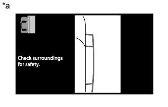
Text in Illustration *a Side Monitor Display Screen display operation
-
After the display conditions are met while the side monitor system is operating normally (when no DTCs are stored), the side monitor display will be displayed.
-
-
Display conditions for manual display mode, when shift lever is in R
-
The side monitor system changes the displayed image when the wide view front and side monitor switch is operated while the following conditions are met and either the ignition switch is ON or the engine is running (no DTCs stored).
Automatic Mode Display Button Accessory Meter Screen Shift Lever Position Vehicle Speed Screen
(Changes Due to Wide View Front and Side Monitor Switch Operation)
OFF Parking assist monitor display R 12 km/h (7.5 mph) or less Side monitor display → Rear monitor display 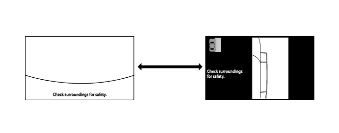
Text in Illustration 
Wide view front and side monitor switch pressed - -
-
-
Display conditions for manual display mode, when shift lever is not in R
-
The side monitor system changes the displayed image when the wide view front and side monitor switch is operated while the following conditions are met and either the ignition switch is ON or the engine is running (no DTCs stored).
Automatic Mode Display Button Accessory Meter Screen Shift Lever Position Vehicle Speed Screen
(Changes Due to Wide View Front and Side Monitor Switch Operation)
OFF Parking assist monitor display Not in R 12 km/h (7.5 mph) or less Side monitor display → Accessory meter display → Wide view front monitor display 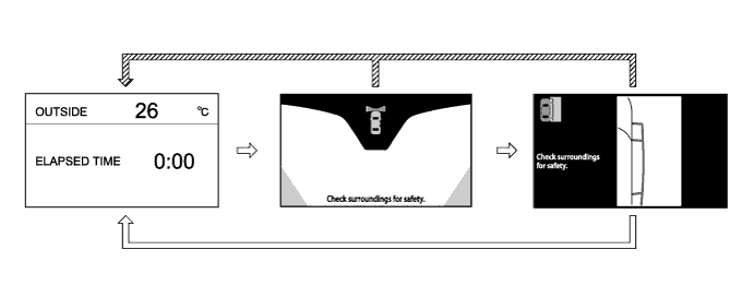
Text in Illustration 
Wide view front and side monitor switch pressed 
When the vehicle speed is more than 12 km/h (7.5 mph)
-
-
-
DISPLAY CONDITIONS FOR MULTI-TERRAIN MONITOR
-
Turn the ignition switch to ON.
Note
Make sure that the vehicle does not move by applying the parking brake firmly.
-
Turn multi-terrain select mode on.
-
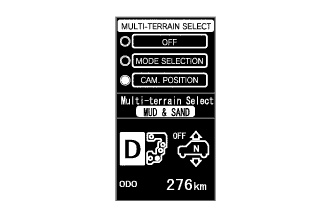
Select "CAM. POSITION".
-
The following are the display conditions for camera selection in multi-terrain select mode when the shift lever is not in R.
Ignition Switch Multi-terrain Select Shift Lever Position Vehicle Speed ON ON Not in R Less than 10 km/h (6.2 mph) 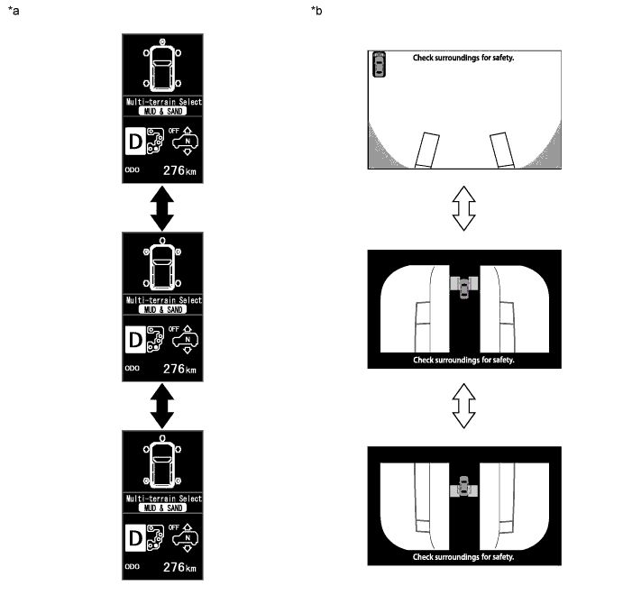
Text in Illustration *a Multi-information Display Outline *b Accessory Meter Outline Multi-information display changes when multi-function switch is pushed up/down Accessory meter changes when multi-function switch is pushed up/down -
The following are the display conditions for camera selection in multi-terrain select mode when the shift lever is in R.
Ignition Switch Multi-terrain Select Shift Lever Position Vehicle Speed ON ON R Less than 10 km/h (6.2 mph) 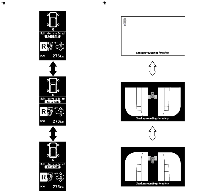
Text in Illustration *a Multi-information Display Outline *b Accessory Meter Outline Multi-information display changes when multi-function switch is pushed up/down Accessory meter changes when multi-function switch is pushed up/down
-