WIDE VIEW FRONT MONITOR SYSTEM Image from Camera for Wide View Front Monitor is Abnormal
DESCRIPTION
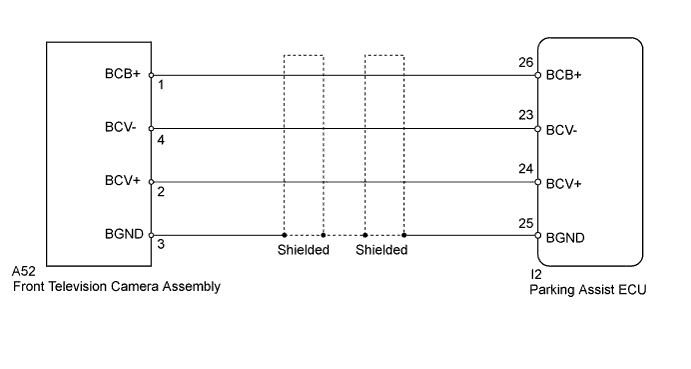
The display signal of the front television camera assembly is transmitted to the parking assist ECU.
WIRING DIAGRAM
INSPECTION PROCEDURE
PROCEDURE
-
CHECK HARNESS AND CONNECTOR (PARKING ASSIST ECU - FRONT TELEVISION CAMERA)
-
Disconnect the I2 parking assist ECU connector.
-
Disconnect the A52 front television camera assembly connector.
-
Measure the resistance according to the value(s) in the table below.
Standard Resistance Tester Connection Condition Specified Condition I2-24 (BCV+) - A52-2 (BCV+) Always Below 1 Ω I2-23 (BCV-) - A52-4 (BCV-) Always Below 1 Ω I2-26 (BCB+) - A52-1 (BCB+) Always Below 1 Ω I2-25 (BGND) - A52-3 (BGND) Always Below 1 Ω I2-24 (BCV+) - Body ground Always 10 kΩ or higher I2-23 (BCV-) - Body ground Always 10 kΩ or higher I2-26 (BGND) - Body ground Always 10 kΩ or higher I2-25 (BCB+) - Body ground Always 10 kΩ or higher
NG 
REPAIR OR REPLACE HARNESS OR CONNECTOR
OK 
-
-
CHECK PARKING ASSIST ECU
-
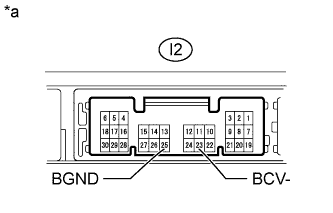
Text in Illustration *a Component without harness connected
(Parking Assist ECU)
Disconnect the I2 parking assist ECU connector.
-
Measure the resistance according to the value(s) in the table below.
Standard Resistance Tester Connection Condition Specified Condition I2-23 (BCV-) - Body ground Always Below 1 Ω I2-25 (BGND) - Body ground Always Below 1 Ω Result Result Proceed to OK A NG (for LHD) B NG (for RHD) C
B
REPLACE PARKING ASSIST ECU Click here
C
REPLACE PARKING ASSIST ECU Click here
A
-
-
CHECK PARKING ASSIST ECU
-
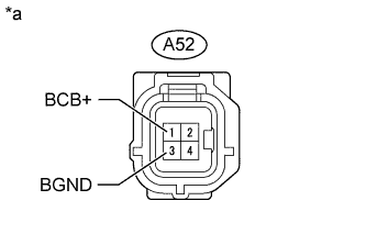
Text in Illustration *a Front view of wire harness connector
(to Front Television Camera Assembly)
Disconnect the A52 front television camera assembly connector.
-
Measure the voltage according to the value(s) in the table below.
Standard Voltage Tester Connection Condition Specified Condition A52-1 (BCB+) - A52-3 (BGND) Wide view front monitor display screen displayed 5.8 to 7.05 V Result Result Proceed to OK A NG (for LHD) B NG (for RHD) C
B
REPLACE PARKING ASSIST ECU Click here
C
REPLACE PARKING ASSIST ECU Click here
A
-
-
CHECK FRONT TELEVISION CAMERA ASSEMBLY
-
Using an oscilloscope, check the waveform.
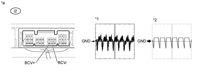
Text in Illustration *a Component with harness connected
(Parking Assist ECU)
- - Measurement Condition Item Content Terminal No. (Symbol) I2-24 (BCV+) - I2-23 (BCV-) Tool Setting
-
0.2 V/DIV., 20 ms/DIV.*1
-
0.2 V/DIV., 50 ms/DIV.*2
Condition
-
Wide view front monitor display screen displayed*1
-
Camera lens covered to make image black while wide view front monitor display screen displayed*2
Result Result Proceed to OK (for LHD) A OK (for RHD) B NG C -
B
REPLACE PARKING ASSIST ECU Click here
C
REPLACE FRONT TELEVISION CAMERA ASSEMBLY Click here
A 
REPLACE PARKING ASSIST ECU Click here
-