WIDE VIEW FRONT MONITOR SYSTEM, Diagnostic DTC:C1681, C1682

| DTC Code | DTC Name |
|---|---|
| C1681 | Front Camera Feedback Malfunction |
| C1682 | Front Camera Current Malfunction |
DESCRIPTION
| DTC Code | DTC Detection Condition | Trouble Area |
|---|---|---|
| C1681 | Front television camera power supply failure |
|
| C1682 | An open or short in the front television camera signal circuit |
|
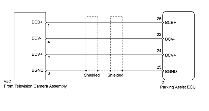
WIRING DIAGRAM
INSPECTION PROCEDURE
Note
When replacing the parking assist ECU, perform initialization of the front television camera.
PROCEDURE
-
CHECK FOR DTC
-
Clear the DTCs Click here.
-
Check for DTCs Click here.
Result Result Proceed to No DTC is output A DTC is output B
B 
CHECK HARNESS AND CONNECTOR (PARKING ASSIST ECU - FRONT TELEVISION CAMERA) Click here
A 
USE SIMULATION METHOD TO CHECK Click here
-
-
CHECK HARNESS AND CONNECTOR (PARKING ASSIST ECU - FRONT TELEVISION CAMERA)
-
Disconnect the I2 parking assist ECU connector.
-
Disconnect the A52 front television camera assembly connector.
-
Measure the resistance according to the value(s) in the table below.
Standard Resistance Tester Connection Condition Specified Condition I2-24 (BCV+) - A52-2 (BCV+) Always Below 1 Ω I2-23 (BCV-) - A52-4 (BCV-) Always Below 1 Ω I2-26 (BCB+) - A52-1 (BCB+) Always Below 1 Ω I2-25 (BGND) - A52-3 (BGND) Always Below 1 Ω I2-24 (BCV+) - Body ground Always 10 kΩ or higher I2-23 (BCV-) - Body ground Always 10 kΩ or higher I2-26 (BGND) - Body ground Always 10 kΩ or higher I2-25 (BCB+) - Body ground Always 10 kΩ or higher
NG 
REPAIR OR REPLACE HARNESS OR CONNECTOR
OK 
-
-
CHECK PARKING ASSIST ECU
-
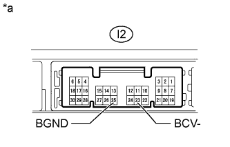
Text in Illustration *a Component without harness connected
(Parking Assist ECU)
Disconnect the I2 parking assist ECU connector.
-
Measure the resistance according to the value(s) in the table below.
Standard Resistance Tester Connection Condition Specified Condition I2-23 (BCV-) - Body ground Always Below 1 Ω I2-25 (BGND) - Body ground Always Below 1 Ω Result Result Proceed to OK A NG (for LHD) B NG (for RHD) C
B
REPLACE PARKING ASSIST ECU Click here
C
REPLACE PARKING ASSIST ECU Click here
A
-
-
CHECK PARKING ASSIST ECU
-
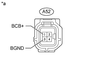
Text in Illustration *a Front view of wire harness connector
(to Front Television Camera Assembly)
Disconnect the A52 front television camera assembly connector.
-
Measure the voltage according to the value(s) in the table below.
Standard Voltage Tester Connection Condition Specified Condition A52-1 (BCB+) - A52-3 (BGND) Wide view front monitor display screen displayed 5.8 to 7.05 V Result Result Proceed to OK A NG (for LHD) B NG (for RHD) C
B
REPLACE PARKING ASSIST ECU Click here
C
REPLACE PARKING ASSIST ECU Click here
A
-
-
CHECK FRONT TELEVISION CAMERA ASSEMBLY
-
Using an oscilloscope, check the waveform.
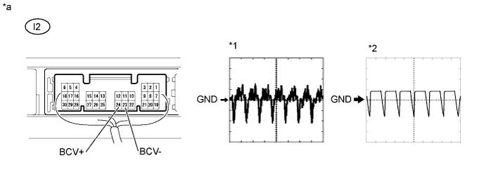
Text in Illustration *a Component with harness connected
(Parking Assist ECU)
- - Measurement Condition Item Content Terminal No. (Symbol) I2-24 (BCV+) - I2-23 (BCV-) Tool Setting
-
0.2 V/DIV., 20 ms/DIV.*1
-
0.2 V/DIV., 50 ms/DIV.*2
Condition
-
Wide view front monitor display screen displayed*1
-
Camera lens covered to make image black while wide view front monitor display screen displayed*2
Result Result Proceed to OK (for LHD) A OK (for RHD) B NG C -
B
REPLACE PARKING ASSIST ECU Click here
C
REPLACE FRONT TELEVISION CAMERA ASSEMBLY Click here
A
REPLACE PARKING ASSIST ECU Click here
-