REAR VIEW MONITOR SYSTEM (w/ Side Monitor System), Diagnostic DTC:C1612

| DTC Code | DTC Name |
|---|---|
| C1612 | IG Voltage is Low or High |
DESCRIPTION
This DTC is stored if the parking assist ECU judges as a result of its self check that the voltage received by terminal IG is low or high.
| DTC Code | DTC Detection Condition | Trouble Area |
|---|---|---|
| C1612 |
|
|
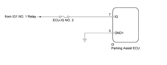
WIRING DIAGRAM
INSPECTION PROCEDURE
Note
Inspect the fuses for circuits related to this system before performing the following inspection procedure.
PROCEDURE
-
READ VALUE USING INTELLIGENT TESTER
-
Connect the intelligent tester to the DLC3.
-
Turn the ignition switch to ON.
-
Turn the intelligent tester on.
-
Enter the following menus: Chassis / Parking Assist Monitor System / Data List.
-
Check the Data List for proper functioning of the following items.
Parking Assist Monitor System Tester Display Measurement Item/Range Normal Condition Diagnostic Note IG Voltage Low Status IG voltage input to parking assist ECU/OK or NG OK: IG voltage is normal
NG: IG voltage is abnormal (too low)
- IG Voltage High Status IG voltage input to parking assist ECU/OK or NG OK: IG voltage is normal
NG: IG voltage is abnormal (too high)
- Result Result Proceed to OK is displayed for both items (for LHD) A OK is displayed for both items (for RHD) B NG is displayed for either item C
B 
REPLACE PARKING ASSIST ECU Click here
C 
CHECK HARNESS AND CONNECTOR (PARKING ASSIST ECU IG VOLTAGE) Click here
A 
REPLACE PARKING ASSIST ECU Click here
-
-
CHECK HARNESS AND CONNECTOR (PARKING ASSIST ECU IG VOLTAGE)
-
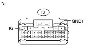
Test in Illustration *a Front view of wire harness connector
(to Parking Assist ECU)
Disconnect the I3 parking assist ECU connector.
-
Measure the voltage according to the value(s) in the table below.
Standard Voltage Tester Connection Switch Condition Specified Condition I3-7 (IG) - I3-3 (GND1) Ignition switch ON 11 to 14 V
NG
REPAIR OR REPLACE HARNESS OR CONNECTOR
OK
USE SIMULATION METHOD TO CHECK Click here
-