TOYOTA PARKING ASSIST-SENSOR SYSTEM (for 8 Sensor Type) Reverse Signal Circuit
DESCRIPTION
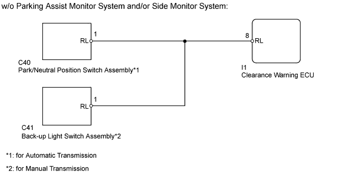
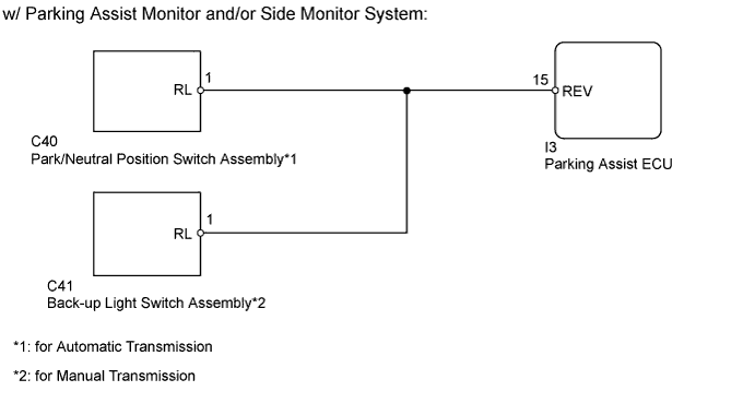
The clearance warning ECU*1 or parking assist ECU*2 receives a reverse shift position signal from the park/neutral position switch assembly*3 or back-up light switch assembly*4.
-
*1: w/o Parking Assist Monitor System and/or Side Monitor System
-
*2: w/ Parking Assist Monitor System and/or Side Monitor System
-
*3: for Automatic Transmission
-
*4: for Manual Transmission
WIRING DIAGRAM
INSPECTION PROCEDURE
PROCEDURE
-
CHECK PARKING ASSIST MONITOR SYSTEM
-
Check if the parking assist monitor system is installed.
Result Result Proceed to w/o Parking Assist Monitor System and/or Side Monitor System A w/ Parking Assist Monitor System and/or Side Monitor System B
B 
CHECK PARKING ASSIST ECU Click here
A 
-
-
CHECK CLEARANCE WARNING ECU
-
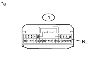
Text in Illustration *a Front view of wire harness connector
(to Clearance Warning ECU)
Disconnect the I1 clearance warning ECU connector.
-
Measure the voltage according to the value(s) in the table below.
Standard Voltage Tester Connection Condition Specified Condition I1-8 (RL) - Body ground Ignition switch ON
Shift lever in R
11 to 14 V I1-8 (RL) - Body ground Ignition switch ON
Shift lever in any position except R
Below 1 V Result Result Proceed to OK A NG (for Automatic Transmission) B NG (for Manual Transmission) C
B
CHECK HARNESS AND CONNECTOR (CLEARANCE WARNING ECU - PARK/NEUTRAL POSITION SWITCH) Click here
C
CHECK HARNESS AND CONNECTOR (CLEARANCE WARNING ECU - BACK-UP LIGHT SWITCH) Click here
A 
PROCEED TO NEXT SUSPECTED AREA SHOWN IN PROBLEM SYMPTOMS TABLE Click here
-
-
CHECK HARNESS AND CONNECTOR (CLEARANCE WARNING ECU - PARK/NEUTRAL POSITION SWITCH)
-
Disconnect the I1 clearance warning ECU connector.
-
Disconnect the C40 park/neutral position switch assembly connector.
-
Measure the resistance according to the value(s) in the table below.
Standard Resistance Tester Connection Condition Specified Condition I1-8 (RL) - C40-1 (RL) Always Below 1 Ω I1-8 (RL) - Body ground Always 10 kΩ or higher
NG 
REPAIR OR REPLACE HARNESS OR CONNECTOR
OK
REPLACE PARK/NEUTRAL POSITION SWITCH ASSEMBLY Click here
-
-
CHECK HARNESS AND CONNECTOR (CLEARANCE WARNING ECU - BACK-UP LIGHT SWITCH)
-
Disconnect the I1 clearance warning ECU connector.
-
Disconnect the C41 back-up light switch assembly connector.
-
Measure the resistance according to the value(s) in the table below.
Standard Resistance Tester Connection Condition Specified Condition I1-8 (RL) - C41-1 (RL) Always Below 1 Ω I1-8 (RL) - Body ground Always 10 kΩ or higher
NG
REPAIR OR REPLACE HARNESS OR CONNECTOR
OK
REPLACE BACK-UP LIGHT SWITCH ASSEMBLY Click here
-
-
CHECK PARKING ASSIST ECU
-
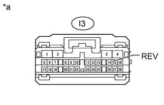
Text in Illustration *a Front view of wire harness connector
(to Parking Assist ECU)
Disconnect the I3 parking assist ECU connector.
-
Measure the voltage according to the value(s) in the table below.
Standard Voltage Tester Connection Condition Specified Condition I3-15 (REV) - Body ground Ignition switch ON
Shift lever in R
11 to 14 V I3-15 (REV) - Body ground Ignition switch ON
Shift lever in any position except R
Below 1 V Result Result Proceed to OK A NG (for Automatic Transmission) B NG (for Manual Transmission) C
B
CHECK HARNESS AND CONNECTOR (PARKING ASSIST ECU - PARK/NEUTRAL POSITION SWITCH) Click here
C
CHECK HARNESS AND CONNECTOR (PARKING ASSIST ECU - BACK-UP LIGHT SWITCH) Click here
A
PROCEED TO NEXT SUSPECTED AREA SHOWN IN PROBLEM SYMPTOMS TABLE Click here
-
-
CHECK HARNESS AND CONNECTOR (PARKING ASSIST ECU - PARK/NEUTRAL POSITION SWITCH)
-
Disconnect the I3 parking assist ECU connector.
-
Disconnect the C40 park/neutral position switch assembly connector.
-
Measure the resistance according to the value(s) in the table below.
Standard Resistance Tester Connection Condition Specified Condition I3-15 (REV) - C40-1 (RL) Always Below 1 Ω I3-15 (REV) - Body ground Always 10 kΩ or higher
NG
REPAIR OR REPLACE HARNESS OR CONNECTOR
OK
REPLACE PARK/NEUTRAL POSITION SWITCH ASSEMBLY Click here
-
-
CHECK HARNESS AND CONNECTOR (PARKING ASSIST ECU - BACK-UP LIGHT SWITCH)
-
Disconnect the I3 parking assist ECU connector.
-
Disconnect the C41 back-up light switch assembly connector.
-
Measure the resistance according to the value(s) in the table below.
Standard Resistance Tester Connection Condition Specified Condition I3-15 (REV) - C41-1 (RL) Always Below 1 Ω I3-15 (REV) - Body ground Always 10 kΩ or higher
NG
REPAIR OR REPLACE HARNESS OR CONNECTOR
OK
REPLACE BACK-UP LIGHT SWITCH ASSEMBLY Click here
-