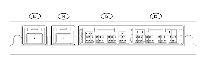
TOYOTA PARKING ASSIST-SENSOR SYSTEM (for 8 Sensor Type) TERMINALS OF ECU

-
CHECK CLEARANCE WARNING ECU (w/o Parking Assist Monitor System and/or Side Monitor System)

-
Measure the voltage and resistance and check for pulse signals according to the value(s) in the table below.
Terminal No. (Symbol) Wiring Color Terminal Description Condition Specified Condition I1-7 (BOR) - I1-17 (E) P - W-B Power source for rear sensor circuit Ignition switch off Below 1.5 V Ignition switch ON, TOYOTA parking assist-sensor system on 7.2 to 8.8 V I1-9 (SOF) - I1-17 (E) V - W-B Front sensor communication signal (Front clearance sonar sensor) Ignition switch ON, TOYOTA parking assist-sensor system on, shift lever in R Pulse generation
(See waveform 2)
I1-10 (BBZ) - I1-17 (E) GR - W-B Clearance warning buzzer signal Ignition switch off Below 1.5 V Ignition switch ON, TOYOTA parking assist-sensor system on 11 to 14 V I1-11 (EF) - I1-17 (E) LG - W-B Ground for clearance warning buzzer When sonar detects obstacle (buzzer sounds) Pulse generation
(See waveform 1)
I1-15 (IG) - I1-17 (E) L - W-B IG power source signal Ignition switch off Below 1.5 V Ignition switch ON 11 to 14 V I1-17 (E) - Body ground W-B - Body ground Ground Always Below 1 Ω I1-18 (E2) - I1-17 (E) R - W-B Ground for rear clearance sonar Always Below 1 Ω I1-19 (E1) - I1-17 (E) G - W-B Ground for rear clearance sonar Always Below 1 Ω I1-21 (BOF) - I1-17 (E) R - W-B Power source for front sensor circuit Ignition switch off Below 1.5 V Ignition switch ON, TOYOTA parking assist-sensor system on 7.2 to 8.8 V I1-24 (SOR) - I1-17 (E) W - W-B Rear sensor communication signal (Rear clearance sonar sensor) Ignition switch ON, TOYOTA parking assist-sensor system on, shift lever in R Pulse generation
(See waveform 2)
-
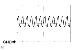
Using an oscilloscope, check waveform 1.
Measurement Condition Item Content Terminal No. (Symbol) I1-11 (EF) - I1-17 (E) Tool Setting 2 V/DIV., 500 μsec./DIV. Vehicle Condition When sonar detects obstacle (Buzzer sounds) -
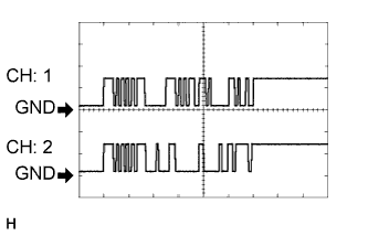
Using an oscilloscope, check waveform 2.
Measurement Condition Item Content Terminal No. (Symbol)
-
CH: 1 I1-9 (SOF) - I1-17 (E)
-
CH: 2 I1-24 (SOR) - I1-17 (E)
Tool Setting 5 V/DIV., 1 msec./DIV. Condition Ignition switch ON, TOYOTA parking assist-sensor system on, shift lever in R -
-
-
CHECK PARKING ASSIST ECU (w/ Parking Assist Monitor System and/or Side Monitor System)
-
Measure the voltage and resistance and check for pulse signals according to the value(s) in the table below.
Terminal No. (Symbol) Wiring Color Terminal Description Condition Specified Condition I2-1 (CSB1) - I3-3 (GND1) R - W-B Power source for front sensor circuit Ignition switch off Below 1.5 V Ignition switch ON, TOYOTA parking assist-sensor system on 7.2 to 8.8 V I2-2 (CSG1) - I3-3 (GND1) G - W-B Ground for front clearance sonar sensor Always Below 1 Ω I2-3 (LIN1) - I3-3 (GND1) V - W-B Front sensor communication signal (Front clearance sonar sensor) Ignition switch ON, TOYOTA parking assist-sensor system on, shift lever in R Pulse generation
(See waveform 1)
I2-7 (CSB2) - I3-3 (GND1) P - W-B Power source for rear sensor circuit Ignition switch off Below 1.5 V Ignition switch ON, TOYOTA parking assist-sensor system on 7.2 to 8.8 V I2-8 (CSG2) - I3-3 (GND1) R - W-B Ground for front clearance sonar sensor Always Below 1 Ω I2-9 (LIN2) - I3-3 (GND1) W - W-B Rear sensor communication signal (Rear clearance sonar sensor) Ignition switch ON, TOYOTA parking assist-sensor system on, shift lever in R Pulse generation
(See waveform 1)
I3-1 (+B) - I3-3 (GND1) L - W-B Power source signal Always 11 to 14 V I3-3 (GND1) - Body ground W-B - Body ground Ground Always Below 1 Ω I3-7 (IG) - I3-3 (GND1) L - W-B IG power source signal Ignition switch ON 11 to 14 V I3-8 (ACC) - I3-3 (GND1) P - W-B ACC power source signal Ignition switch ACC 11 to 14 V I3-9 (CSSW) - I3-3 (GND1) V - W-B Clearance sensor main switch signal Ignition switch ON, clearance sensor main switch on 11 to 14 V Ignition switch ON, clearance sensor main switch off Below 1 V I3-15 (REV) - I3-3 (GND1) R - W-B Reverse signal Ignition switch ON, shift lever in R 11 to 14 V Ignition switch ON, shift lever not in R Below 1 V I3-17 (EF) - I3-3 (GND1) LG - W-B Ground for clearance warning buzzer Buzzer sounding Pulse generation
(See waveform 2)
I3-18 (BBZ) - I3-3 (GND1) GR - W-B Clearance warning buzzer signal Ignition switch off Below 1.5 V Ignition switch ON, TOYOTA parking assist-sensor system on 11 to 14 V I3-24 (TX-) LG AVC-LAN communication signal - - I3-25 (TX+) L AVC-LAN communication signal - - -
Using an oscilloscope, check waveform 1.
Measurement Condition Item Content Terminal No. (Symbol)
-
CH: 1 I2-3 (LIN1) - I3-3 (GND1)
-
CH: 2 I2-9 (LIN2) - I3-3 (GND1)
Tool Setting 5 V/DIV., 1 msec./DIV. Condition Ignition switch ON, TOYOTA parking assist-sensor system on, shift lever in R -
-
Using an oscilloscope, check waveform 2.
Measurement Condition Item Content Terminal No. (Symbol) I3-17 (EF) - I3-3 (GND1) Tool Setting 2 V/DIV., 500 μsec./DIV. Vehicle Condition When sonar detects obstacle (Buzzer sounds)
-
-
CHECK DRIVING SUPPORT SWITCH CONTROL ECU

-
Measure the resistance according to the value(s) in the table below.
Terminal No. (Symbol) Wiring Color Terminal Description Condition Specified Condition G76-3 (SWI1) - G76-4 (SWI2) SB - P Steering pad switch assembly input signal (Menu, ENTER, Up, or Down switch) Ignition switch ON, Menu, ENTER, Up, or Down switch pressed Below 1V Ignition switch ON, Menu, ENTER, Up, or Down switch not pressed 11 to 14 V G76-4 (SWI2) - Body ground P - Body ground Steering pad switch assembly input signal (Menu, ENTER, Up, or Down switch) Always Below 1 V G76-12 (SWO1) - Body ground V - Body ground Steering pad switch assembly output signal (Menu, ENTER, Up, or Down switch) Ignition switch ON, Menu, ENTER, Up, or Down switch pressed to turn TOYOTA parking assist-sensor system on Below 1V Ignition switch ON, Menu, ENTER, Up, or Down switch not pressed 11 to 14 V
-