LIGHTING SYSTEM Stop Light Circuit
DESCRIPTION
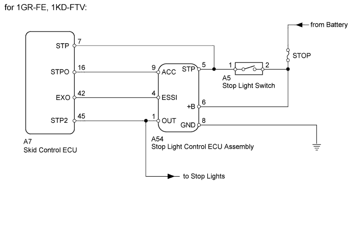
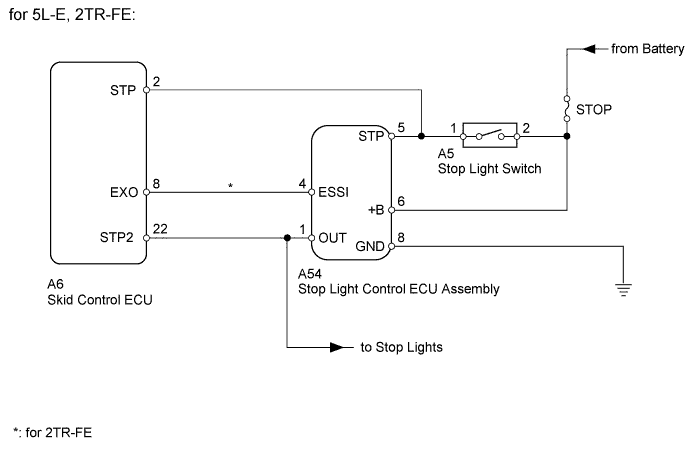
When the stop light switch is turned on, current flows to the stop lights to illuminate them. During emergency braking, the brake control system blinks all stop lights to alert following drivers and reduces the possibility of a rear-end collision.
WIRING DIAGRAM
INSPECTION PROCEDURE
PROCEDURE
-
CHECK FOR DTC (BRAKE CONTROL SYSTEM)
-
Clear the DTCs Click here for 5L-E, Click here for 1GR-FE, 1KD-FTV, Click here for 2TR-FE).
-
Check for DTCs Click here for 5L-E, Click here for 1GR-FE, 1KD-FTV, Click here for 2TR-FE).
OK DTC output does not occur. Result Result Proceed to OK A NG (for 5L-E) B NG (for 1GR-FE, 1KD-FTV) C NG (for 2TR-FE) D
B 
GO TO ANTI-LOCK BRAKE SYSTEM Click here
C
GO TO VEHICLE STABILITY CONTROL SYSTEM (for Hydraulic Brake Booster) Click here
D
GO TO VEHICLE STABILITY CONTROL SYSTEM (for Vacuum Brake Booster) Click here
A 
-
-
INSPECT STOP LIGHT SWITCH ASSEMBLY
-
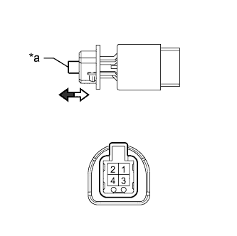
Text in Illustration *a Pin 
Pin released 
Pin pushed Remove the stop light switch Click here.
-
Measure the resistance according to the value(s) in the table below.
Standard Resistance Tester Connection Switch Condition Specified Condition 1-2 Pin released Below 8.3 Ω Pin pushed 10 kΩ or higher
NG
REPLACE STOP LIGHT SWITCH ASSEMBLY Click here
OK
-
-
CHECK HARNESS AND CONNECTOR (STOP LIGHT SWITCH ASSEMBLY - BATTERY)
-
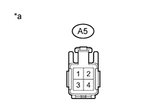
Text in Illustration *a Front view of wire harness connector
(to Stop Light Control ECU Assembly)
Disconnect the A5 stop light switch connector.
-
Measure the voltage according to the value(s) in the table below.
Standard Voltage Tester Connection Condition Specified Condition A5-2 - Body ground Always 11 to 14 V
NG
REPAIR OR REPLACE HARNESS OR CONNECTOR
OK
-
-
CHECK HARNESS AND CONNECTOR (STOP LIGHT CONTROL ECU ASSEMBLY - BATTERY AND BODY GROUND)
-
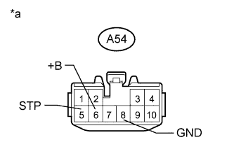
Text in Illustration *a Front view of wire harness connector
(to Stop Light Control ECU Assembly)
Disconnect the A54 stop light control ECU connector.
-
Measure the voltage according to the value(s) in the table below.
Standard Voltage Tester Connection Condition Specified Condition A54-5 (STP) - Body ground Brake pedal depressed 11 to 14 V A54-5 (STP) - Body ground Brake pedal released Below 1 V A54-6 (+B) - Body ground Always 11 to 14 V -
Measure the resistance according to the value(s) in the table below.
Standard Resistance Tester Connection Condition Specified Condition A54-8 (GND) - Body ground Always Below 1 Ω Result Result Proceed to OK (Problem is that lights are flashing) (except 5L-E) A OK (Problem is that lights do not turn on or stay on) B NG C
B
PROCEED TO NEXT SUSPECTED AREA SHOWN IN PROBLEM SYMPTOMS TABLE Click here
C
REPAIR OR REPLACE HARNESS OR CONNECTOR
A
-
-
CHECK STOP LIGHT
-
With the skid control ECU connector disconnected, check the illumination of the stop lights when depressing the brake pedal.
OK Stop lights operate normally when the brake pedal is depressed.
NG
REPLACE STOP LIGHT CONTROL ECU ASSEMBLY Click here
OK 
REPLACE SKID CONTROL ECU Click here
-