LIGHTING SYSTEM TERMINALS OF ECU

-
CHECK HEADLIGHT SWIVEL ECU ASSEMBLY

-
Disconnect the A58 headlight swivel ECU connector.
-
Measure the resistance and voltage according to the value(s) in the table below.
Terminal No. (Symbol) Wiring Color Terminal Description Condition Specified Condition A58-22 (E1) - Body ground W-B - Body ground Headlight swivel ECU ground Always Below 1 Ω A58-14 (IGS) - Body ground L - Body ground Swivel motor power supply Ignition switch off Below 1 V Ignition switch ON 11 to 14 V A58-15 (IG) - Body ground G - Body ground Headlight swivel ECU power supply Ignition switch off Below 1 V Ignition switch ON 11 to 14 V If the result is not as specified, there may be a malfunction on the wire harness side.
-
Reconnect the A58 headlight swivel ECU connector.
-
Measure the resistance and voltage according to the value(s) in the table below.
Terminal No. (Symbol) Wiring Color Terminal Description Condition Specified Condition A58-21 (SGF) - A58-22 (E1) W - W-B Rear height control sensor ground Always Below 1 Ω A58-23 (SMGL) - A58-22 (E1) G - W-B Swivel motor LH ground Always Below 1 Ω A58-24 (SMGR) - A58-22 (E1) P - W-B Swivel motor RH ground Always Below 1 Ω A58-27 (LH-) - A58-22 (E1) LG - W-B Leveling motor LH ground Always Below 1 Ω A58-28 (RH-) - A58-22 (E1) LG - W-B Leveling motor RH ground Always Below 1 Ω A58-1 (SMBL) - A58-22 (E1) V - W-B Swivel motor LH power supply Ignition switch off Below 1 V Ignition switch ON 11 to 16 V A58-2 (SMBR) - A58-22 (E1) B - W-B Swivel motor RH power supply Ignition switch off Below 1 V Ignition switch ON 11 to 16 V A58-3 (LHT) - A58-22 (E1) L - W-B Leveling motor LH power supply Ignition switch off Below 1 V Ignition switch ON 11 to 16 V A58-4 (RHT) - A58-22 (E1) GR - W-B Leveling motor RH power supply Ignition switch off Below 1 V Ignition switch ON 11 to 16 V A58-7 (INIT) - A58-22 (E1) R - W-B Initialization signal Ignition switch ON, terminals LVL and GND of DLC3 connected Below 1 V Ignition switch ON, terminals LVL and GND of DLC3 not connected Approx. 5 V A58-10 (SMR) - A58-22 (E1) L - W-B Swivel motor RH LIN communication Ignition switch off Below 1 V Ignition switch ON Pulse generation A58-11 (RH+) - A58-22 (E1) R - W-B Leveling motor RH LIN communication Ignition switch off Below 1 V Ignition switch ON Pulse generation A58-18 (SBF) - A58-21 (SGF) R-G - W Rear height control sensor power supply Ignition switch off Below 1 V Ignition switch ON Approx. 5 V A58-19 (SHRL) - A58-21 (SGF) B-R - W Rear height control sensor signal Ignition switch off Below 1 V Ignition switch ON 1 to 4 V A58-29 (SML) - A58-22 (E1) W - W-B Swivel motor LH LIN communication Ignition switch off Below 1 V Ignition switch ON Pulse generation A58-30 (LH+) - A58-22 (E1) R - W-B Leveling motor LH LIN communication Ignition switch off Below 1 V Ignition switch ON Pulse generation If the result is not as specified, the headlight swivel ECU may have a malfunction.
-
-
CHECK DRIVER SIDE JUNCTION BLOCK ASSEMBLY, MAIN BODY ECU (MULTIPLEX NETWORK BODY ECU)

Text in Illustration *A for LHD *B for RHD
-
Remove the main body ECU Click here.
-
Measure the resistance and voltage according to the value(s) in the table below.
Terminal No. (Symbol) Wiring Color Terminal Description Condition Specified Condition A-29 (ACC) - Body ground - ACC power supply Ignition switch ACC 11 to 14 V A-30 (BECU) - Body ground - Battery power supply Always 11 to 14 V A-32 (IG) - Body ground - Ignition power supply Ignition switch ON 11 to 14 V A-11 (GND1) - Body ground - Ground Always Below 1 Ω G63-3 (GND2) - Body ground W-B - Body ground Ground Always Below 1 Ω If the result is not as specified, there may be a malfunction on the wire harness side.
-
Install the main body ECU Click here.
-
Measure the voltage according to the value(s) in the table below.
Terminal No. (Symbol) Wiring Color Terminal Description Condition Specified Condition G63-23 (RFOG) - 2D-4 (GND1)*5 SB - W-B Rear fog light switch input Rear fog light switch on Below 1 V Rear fog light switch off 11 to 14 V G64-1 (GCTY) - 2D-4 (GND1)*6 V - W-B Glass hatch courtesy light switch signal Glass hatch open Below 1 V Glass hatch closed 11 to 14 V G64-3 (HAZ) - 2D-4 (GND1) W - W-B Hazard warning signal switch output Hazard warning signal switch on 11 to 14 V Hazard warning signal switch off Below 1 V G64-5 (HU) - 2D-4 (GND1) LG - W-B Headlight dimmer switch high signal input Headlight dimmer switch in high Below 1 V Headlight dimmer switch in low 11 to 14 V G64-6 (RCTY) - 2D-4 (GND1)*7 R - W-B Rear door courtesy light switch RH signal Rear door RH open Below 1 V Rear door RH closed 11 to 14 V G64-8 (HF) - 2D-4 (GND1) V - W-B Headlight dimmer switch high flash signal input Headlight dimmer switch in high flash position Below 1 V Headlight dimmer switch not in high flash position 11 to 14 V G64-15 (DIM) - 2D-4 (GND1) P - W-B H-LP HI relay drive output Headlight dimmer switch in high or high flash Below 1 V Headlight dimmer switch not in high or high flash 11 to 14 V G64-19 (BCTY) - 2D-4 (GND1) G - W-B Back door courtesy light switch signal Back door open Below 1 V Back door closed 11 to 14 V G64-20 (CLTB) - 2D-4 (GND1)*3 P - W-B Automatic light control sensor power supply output Ignition switch off Below 1 V Ignition switch ON and headlight dimmer switch in AUTO position 11 to 14 V G64-21 (CLTS) - 2D-4 (GND1)*3 R - W-B Automatic light control sensor signal input Ignition switch off Below 1 V Automatic light control system operates Pulse generation
(See waveform 1)
G64-27 (FFOG) - 2D-4 (GND1)*4 G - W-B Front fog light switch input Front fog light switch on Below 1 V Front fog light switch off 11 to 14 V G64-28 (A) - 2D-4 (GND1)*3 W - W-B Headlight dimmer switch AUTO signal input Headlight dimmer switch in AUTO Below 1 V Headlight dimmer switch not in AUTO 11 to 14 V G64-29 (HEAD) - 2D-4 (GND1) SB - W-B Headlight dimmer switch head signal input Headlight dimmer switch in head Below 1 V Headlight dimmer switch not in head 11 to 14 V G64-30 (TAIL) - 2D-4 (GND1) W - W-B Headlight dimmer switch tail signal input Headlight dimmer switch in tail or head Below 1 V Headlight dimmer switch in neither tail nor head 11 to 14 V G65-3 (LCTY) - 2D-4 (GND1)*7 V - W-B Rear door courtesy light switch LH signal Rear door LH open Below 1 V Rear door LH closed 11 to 14 V 2D-15 (FRCY) - 2D-4 (GND1)*1
2H-26 (FRCY) - 2D-4 (GND1)*2
B - W-B Front door courtesy light switch RH signal Front door RH open Below 1 V Front door RH closed 11 to 14 V 2F-7 (TRLY) - 2D-4 (GND1) LG - W-B Clearance light signal output Headlight dimmer switch in tail position 11 to 14 V Headlight dimmer switch not in tail position Below 1 V 2F-9 (FFGO) - 2D-4 (GND1)*4 W - W-B Front fog light signal output Headlight dimmer switch in tail and front fog light switch on Below 1 V Front fog light switch off 11 to 14 V 2F-19 (RFGO) - 2D-4 (GND1)*5 GR-L - W-B Rear fog light signal output Headlight dimmer switch in tail and rear fog light switch on Below 1 V Rear fog light switch off 11 to 14 V 2F-40 (HRLY) - 2D-4 (GND1) GR - W-B H-LP LO relay drive output Headlight dimmer switch in head Below 1 V Headlight dimmer switch not in head 11 to 14 V 2I-16 (TRLY) - 2D-4 (GND1)*1
2D-32 (TRLY) - 2D-4 (GND1)*2
LG - W-B Taillight and license plate light signal output Headlight dimmer switch in tail position 11 to 14 V Headlight dimmer switch not in tail position Below 1 V 2I-27 (FLCY) - 2D-4 (GND1)*1
2D-31 (FLCY) - 2D-4 (GND1)*2
R - W-B Front door courtesy light switch LH signal Front door LH open Below 1 V Front door LH closed 11 to 14 V 2K-1 (TRLY) - 2D-4 (GND1) B - W-B Battery power supply Always 11 to 14 V
-
*1: for LHD
-
*2: for RHD
-
*3: w/ Automatic Light Control System
-
*4: w/ Front Fog Light
-
*5: w/ Rear Fog Light
-
*6: w/ Glass Hatch Opener System
-
*7: for 5 Door
If the result is not as specified, the main body ECU may have a malfunction.
-
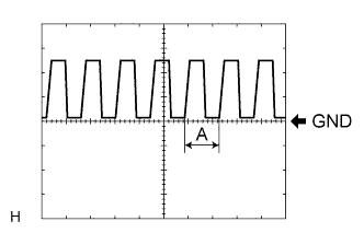
Waveform 1
Item Content Terminal No. (Symbol) G64-21 (CLTS) - 2D-4 (GND1) Tool setting 5 V/DIV., 5 ms./DIV. Condition Ignition switch ON
Headlight dimmer switch AUTO
Automatic light control sensor covered with a hand → Automatic light control sensor exposed to ambient light
Tech Tips
When the ambient light becomes brighter, width A becomes narrower.
-
-