HEADLIGHT ASSEMBLY (for Halogen Headlight) INSTALLATION

Tech Tips
-
Use the same procedure for the RH and LH sides.
-
The procedure listed below is for the LH side.
-
INSTALL HEADLIGHT ASSEMBLY LH
-
Connect the connectors.
-
Attach the clamp to install the headlight.
-
Install the bolt and 2 screws.
-
-
INSTALL FRONT BUMPER BAR REINFORCEMENT LH
-
Install the front bumper reinforcement with the 6 nuts.
- Torque:
- 30 N*m { 306 kgf*cm, 21 ft.*lbf }
-
-
INSTALL FRONT BUMPER COVER
-
Install the lower front bumper cover with the 5 bolts and clip.
-
-
INSTALL RADIATOR GRILLE
-
Install the radiator grille Click here.
-
-
PREPARATION FOR HEADLIGHT AIMING ADJUSTMENT (Using a screen)
-
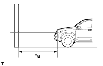
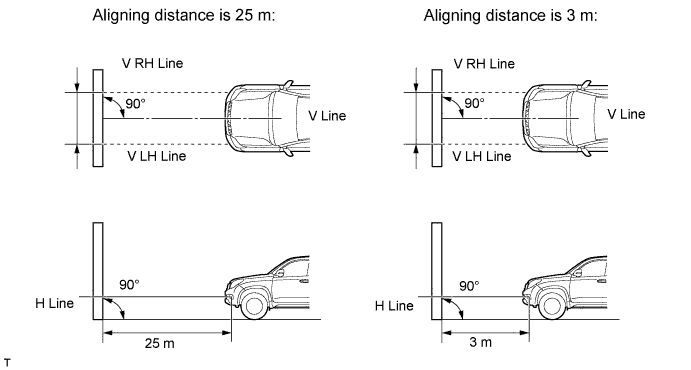
Text in Illustration *a 25 or 3 m Prepare the vehicle (except China and Taiwan):
-
Place the vehicle in a location that is dark enough to clearly observe the cutoff line. The cutoff line is a distinct line, below which light from the headlights can be observed and above which it cannot.
-
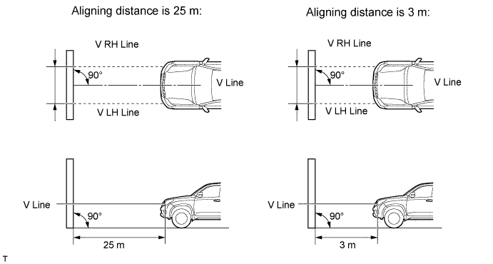
Place the vehicle at a 90° angle to the wall.
-
Create a 25 m (82.0 ft.) distance between the vehicle (headlight bulb center) and wall.
-
Make sure that the vehicle is on a level surface.
-
Bounce the vehicle up and down to settle the suspension.
Note
A distance of 25 m (82.0 ft.) between the vehicle (headlight bulb center) and wall is necessary for proper aim adjustment. If unavailable, secure a distance of exactly 3 m (9.84 ft.) for the check and adjustment (the target zone will change with the distance, so follow the instructions in the illustration).
-
-
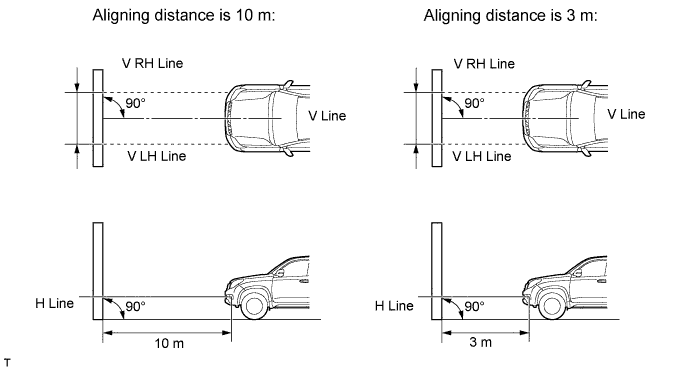
Text in Illustration *a 10 or 3 m Prepare the vehicle (for China and Taiwan):
-
Place the vehicle in a location that is dark enough to clearly observe the cutoff line. The cutoff line is a distinct line, below which light from the headlights can be observed and above which it cannot.
-
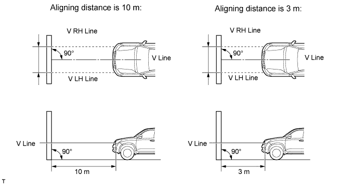
Place the vehicle at a 90° angle to the wall.
-
Create a 10 m (32.8 ft) distance between the vehicle (headlight bulb center) and the wall.
-
Make sure that the vehicle is on a level surface.
-
Bounce the vehicle up and down to settle the suspension.
Note
A distance of 10 m (32.8 ft) between the vehicle (headlight bulb center) and the wall is necessary for proper aim adjustment. If unavailable, secure a distance of exactly 3 m (9.84 ft) for check and adjustment. (The target zone will change with the distance so follow the instructions in the illustration.)
-
-
Prepare a piece of thick white paper approximately 2 m (6.56 ft.) (height) x 4 m (13.1 ft.) (width) to use as a screen.
-
Draw a vertical line down the center of the screen (V line).
-
except China and Taiwan:
Set the screen as shown in the illustration.
Tech Tips
-
Stand the screen perpendicular to the ground.
-
Align the V line on the screen with the center of the vehicle.
-
-
for China and Taiwan:
Set the screen as shown in the illustration.
Tech Tips
-
Stand the screen perpendicular to the ground.
-
Align the V line on the screen with the center of the vehicle.
-
-
Prepare a piece of thick white paper approximately 2 m (6.56 ft.) (height) x 4 m (13.1 ft.) (width) to use as a screen.
-
Draw a vertical line down the center of the screen (V line).
-
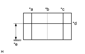
Text in Illustration *a V LH Line *b V Line *c V RH Line *d H Line *e Ground Draw base lines (H, V LH, and V RH Lines) on the screen as shown in the illustration.
Tech Tips
-
The base lines differ for "low beam inspection" and "high beam inspection".
-
Mark the headlight bulb center marks on the screen. If the center mark cannot be observed on the headlight, use the center of the headlight bulb or the name of the manufacturer marked on the headlight as the center mark.
-
H Line (Headlight):
Draw a horizontal line across the screen so that it passes through the center marks. The H line should be at the same height as the headlight bulb center marks of the low beam headlights.
-
V LH Line, V RH Line (Center mark position of the left-hand (LH) and right-hand (RH) headlights):
Draw two vertical lines so that they intersect the H line at each center mark (aligned with the center of the low beam headlight bulbs).
-
-
-
INSPECT HEADLIGHT AIMING
-
Cover the headlight or disconnect the connector of the headlight on the opposite side to prevent light from the headlight that is not being inspected from affecting the headlight aiming.
Note
Do not keep the headlight covered for more than 3 minutes. The headlight lens is made of synthetic resin, which may melt or be damaged due to excessive heat.
Tech Tips
When checking the aim of the high beam headlight, cover the low beam headlight or disconnect the connector.
-
Start the engine.
-
except China and Taiwan:
Turn on the headlight and check if the cutoff line matches the preferred cutoff line in the following illustration.
Tech Tips
-
Since the low beam light and the high beam light are a unit, if the aim on the low beam is correct, the high beam should also be correct. However, check both beams just to make sure.
-
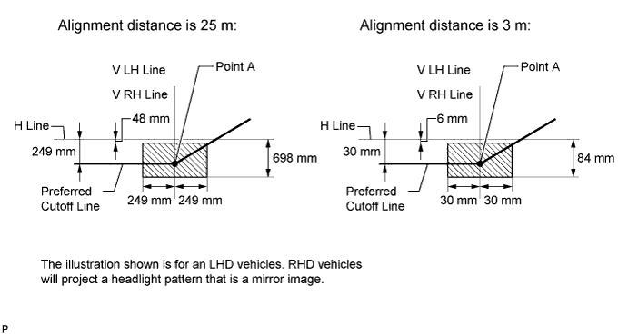
If the alignment distance is 25 m (82.0 ft.):
The low beam cutoff line should be within 48 mm (1.89 in.) and 698 mm (2.29 ft.) below the H line as well as 249 mm (9.80 in.) left or right of the V LH or V RH line.
-
If the alignment distance is 3 m (9.84 ft.):
The low beam cutoff line should be within 6 mm (0.24 in.) and 84 mm (3.30 in.) below the H line as well as 30 mm (1.18 in.) left or right of the V LH or V RH line.
-
If the alignment distance is 25 m (82.0 ft.):
The horizontal line of the preferred low beam cutoff line is 249 mm (9.80 in.) below the H line and point A of the preferred low beam cutoff line is on the V LH or V RH line.
-
If the alignment distance is 3 m (9.84 ft.):
The horizontal line of the preferred low beam cutoff line is 30 mm (1.18 in.) below the H line and point A of the preferred low beam cutoff line is on the V LH or V RH line.
-
-
for China:
Turn on the headlight and check if the cutoff line matches the preferred cutoff line in the following illustration.
Tech Tips
-
Since the low beam light and the high beam light are a unit, if the aim on the low beam is correct, the high beam should also be correct. However, check both beams just to make sure.
-
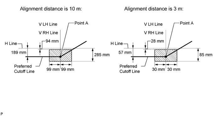
If the alignment distance is 10 m (32.8 ft.):
The low beam cutoff line should be within 94 mm (3.70 in.) and 285 mm (11.2 in.) below the H line as well as 99 mm (3.89 in.) left or right of the V LH or V RH line.
-
If the alignment distance is 3 m (9.84 ft.):
The low beam cutoff line should be within 28 mm (1.10 in.) and 85 mm (3.34 in.) below the H line as well as 30 mm (1.18 in.) left or right of the V LH or V RH line.
-
If the alignment distance is 10 m (32.8 ft.):
The horizontal line of the preferred low beam cutoff line is 189 mm (7.44 in.) below the H line and point A of the preferred low beam cutoff line is on the V LH or V RH line.
-
If the alignment distance is 3 m (9.84 ft.):
The horizontal line of the preferred low beam cutoff line is 57 mm (2.24 in.) below the H line and point A of the preferred low beam cutoff line is on the V LH or V RH line.
-
-
for Taiwan:
Turn on the headlight and check if the cutoff line matches the preferred cutoff line in the following illustration.
Tech Tips
-
Since the low beam light and the high beam light are a unit, if the aim on the low beam is correct, the high beam should also be correct. However, check both beams just to make sure.
-
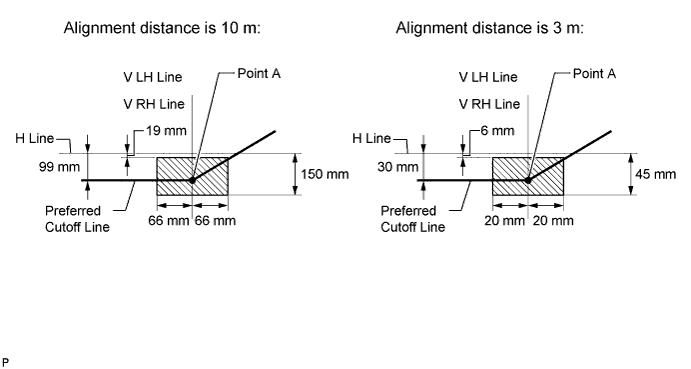
If the alignment distance is 10 m (32.8 ft.):
The low beam cutoff line should be within 19 mm (0.74 in.) and 150 mm (5.90 in.) below the H line as well as 66 mm (2.59 in.) left or right of the V LH or V RH line.
-
If the alignment distance is 3 m (9.84 ft.):
The low beam cutoff line should be within 6 mm (0.23 in.) and 45 mm (1.77 in.) below the H line as well as 20 mm (0.78 in.) left or right of the V LH or V RH line.
-
If the alignment distance is 10 m (32.8 ft.):
The horizontal line of the preferred low beam cutoff line is 99 mm (3.89 in.) below the H line and point A of the preferred low beam cutoff line is on the V LH or V RH line.
-
If the alignment distance is 3 m (9.84 ft.):
The horizontal line of the preferred low beam cutoff line is 30 mm (1.18 in.) below the H line and point A of the preferred low beam cutoff line is on the V LH or V RH line.
-
-
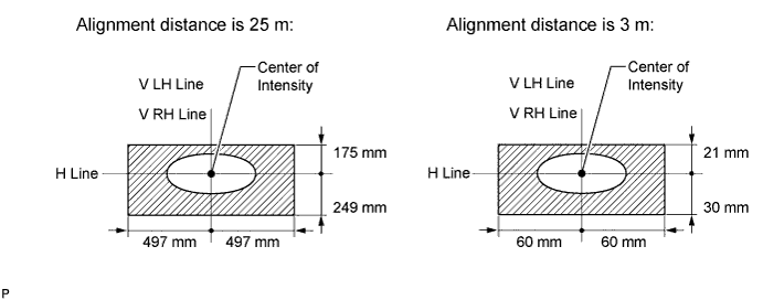
except China and Taiwan:
Turn on the high beams and check if the center of intensity for each high beam matches the center of intensity in the illustration.
Tech Tips
-
Since the low beam light and the high beam light are a unit, if the aim on the low beam is correct, the high beam should also be correct. However, check both beams just to make sure.
-
If the alignment distance is 25 m (82.0 ft.):
The high beam center of intensity should be within 175 mm (6.88 in.) above and 249 mm (9.80 in.) below the H line as well as 497 mm (1.63 ft.) left or right of the V LH or V RH line.
-
If the alignment distance is 3 m (9.84 ft.):
The high beam center of intensity should be within 21 mm (0.82 in.) above and 30 mm (1.18 in.) below the H line as well as 60 mm (2.36 in.) left or right of the V LH or V RH line.
-
-
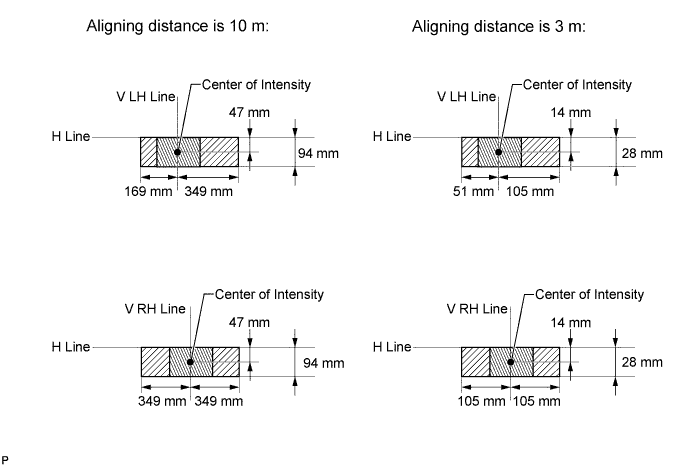
for China:
Turn on the high beams and check if the center of intensity for each high beam matches the center of intensity in the illustration.
Tech Tips
-
Since the low beam light and the high beam light are a unit, if the aim on the low beam is correct, the high beam should also be correct. However, check both beams just to make sure.
-
If the alignment distance is 10 m (32.8 ft.):
The high beam center of intensity should be within 47 mm (1.85 in.) below the H line.
-
If the alignment distance is 3 m (9.84 ft.):
The high beam center of intensity should be within 14 mm (0.55 in.) below the H line.
-
If the alignment distance is 10 m (32.8 ft.):
The high beam center of intensity for the headlight assembly LH should be within 169 mm (6.65 in.) left and 349 mm (1.14 ft.) right of the V LH line.
-
If the alignment distance is 3 m (9.84 ft.):
The high beam center of intensity for the headlight assembly LH should be within 51 mm (2.0 in.) left and 105 mm (4.13 in.) right of the V LH line.
-
If the alignment distance is 10 m (32.8 ft.):
The high beam center of intensity for the headlight assembly RH should be within 349 mm (1.14 ft.) left or right of the V RH line.
-
If the alignment distance is 3 m (9.84 ft.):
The high beam center of intensity for the headlight assembly RH should be within 105 mm (4.13 in.) left or right of the V RH line.
-
-
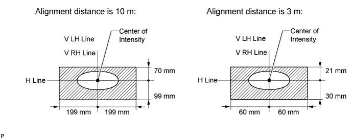
for Taiwan:
Turn on the high beams and check if the center of intensity for each high beam matches the center of intensity in the illustration.
Tech Tips
-
Since the low beam light and the high beam light are a unit, if the aim on the low beam is correct, the high beam should also be correct. However, check both beams just to make sure.
-
If the alignment distance is 10 m (32.8 ft.):
The high beam center of intensity should be within 70 mm (2.75 in.) above and 99 mm (3.89 in.) below the H line as well as 198 mm (7.79 in.) left or right of the V LH or V RH line.
-
If the alignment distance is 3 m (9.84 ft.):
The high beam center of intensity should be within 21 mm (0.82 in.) above and 30 mm (1.18 in.) below the H line as well as 59 mm (2.32 in.) left or right of the V LH or V RH line.
-
-
-
ADJUST HEADLIGHT AIMING
-
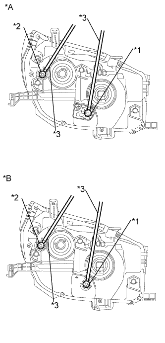
Text in Illustration *A w/ Headlight Leveling *B w/o Headlight Leveling *1 Vertical Aiming *2 Horizontal Aiming *3 Screwdriver Adjust the aim vertically:
Adjust the aim of each headlight to the specified range by turning each aiming screw with a screwdriver.
Note
The final turn of the aiming screw should be made in the clockwise direction. If the screw is tightened excessively, loosen it, and then retighten it so that the final turn of the screw is in the clockwise direction.
Tech Tips
-
Since the low beam light and the high beam light are a unit, if the aim on the low beam is correct, the high beam should also be correct. However, check both beams just to make sure.
-
If it is not possible to correctly adjust headlight aim, check the bulb, headlight unit and headlight unit reflector installation.
-
The headlight aim moves up when turning the vertical aiming screw clockwise, and moves down when turning the vertical aiming screw counterclockwise. The headlight aim moves right when turning the horizontal aiming screw clockwise, and moves left when turning the horizontal aiming screw counterclockwise.
-
Confirm the direction of rotation of the aiming screw by observing it while it is being adjusted. Due to the position of the screwdriver, the direction of rotation of the adjusting screw can be different than the direction of rotation of the screwdriver being used to adjust it.
-
-
Adjust the aim horizontally:
Adjust the aim of each headlight to the specified range by turning each aiming screw with a screwdriver.
Note
The final turn of the aiming screw should be made in the clockwise direction. If the screw is tightened excessively, loosen it, and then retighten it so that the final turn of the screw is in the clockwise direction.
Tech Tips
-
Since the low beam light and the high beam light are a unit, if the aim on the low beam is correct, the high beam should also be correct. However, check both beams just to make sure.
-
If it is not possible to correctly adjust headlight aim, check the bulb, headlight unit and headlight unit reflector installation.
-
Confirm the direction of rotation of the aiming screw by observing it while it is being adjusted. Due to the position of the screwdriver, the direction of rotation of the adjusting screw can be different than the direction of rotation of the screwdriver being used to adjust it.
-
-
-
PREPARATION FOR FOG LIGHT AIMING
-
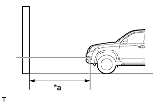
Text in Illustration *a 25 or 3 m Prepare the vehicle (except China and Taiwan):
-
Place the vehicle in a location that is dark enough to clearly observe the cutoff line. The cutoff line is a distinct line, below which light from the headlights can be observed and above which it cannot.
-
Place the vehicle at a 90° angle to the wall.
-
Create a 25 m (82.0 ft.) distance between the vehicle (headlight bulb center) and wall.
-
Make sure that the vehicle is on a level surface.
-
Bounce the vehicle up and down to settle the suspension.
Note
A distance of 25 m (82.0 ft.) between the vehicle (headlight bulb center) and wall is necessary for proper aim adjustment. If unavailable, secure a distance of exactly 3 m (9.84 ft.) for the check and adjustment (the target zone will change with the distance, so follow the instructions in the illustration).
-
-
Text in Illustration *a 10 or 3 m Prepare the vehicle (for China and Taiwan):
-
Place the vehicle in a location that is dark enough to clearly observe the cutoff line. The cutoff line is a distinct line, below which light from the headlights can be observed and above which it cannot.
-
Place the vehicle at a 90° angle to the wall.
-
Create a 10 m (32.8 ft) distance between the vehicle (headlight bulb center) and the wall.
-
Make sure that the vehicle is on a level surface.
-
Bounce the vehicle up and down to settle the suspension.
Note
A distance of 10 m (32.8 ft) between the vehicle (headlight bulb center) and the wall is necessary for proper aim adjustment. If unavailable, secure a distance of exactly 3 m (9.84 ft) for check and adjustment. (The target zone will change with the distance so follow the instructions in the illustration.)
-
-
Prepare a piece of thick white paper approximately 2 m (6.56 ft.) (height) x 4 m (13.1 ft.) (width) to use as a screen.
-
Draw a vertical line down the center of the screen (V line).
-
except China and Taiwan:
Set the screen as shown in the illustration.
Tech Tips
-
Stand the screen perpendicular to the ground.
-
Align the V line on the screen with the center of the vehicle.
-
-
for China and Taiwan:
Set the screen as shown in the illustration.
Tech Tips
-
Stand the screen perpendicular to the ground.
-
Align the V line on the screen with the center of the vehicle.
-
-
Prepare a piece of thick white paper approximately 2 m (6.56 ft.) (height) x 4 m (13.1 ft.) (width) to use as a screen.
-
Draw a vertical line down the center of the screen (V line).
-
Text in Illustration *a V LH Line *b V Line *c V RH Line *d H Line *e Ground Draw base lines (H, V LH, and V RH Lines) on the screen as shown in the illustration.
Tech Tips
-
The base lines differ for "low beam inspection" and "high beam inspection".
-
Mark the headlight bulb center marks on the screen. If the center mark cannot be observed on the headlight, use the center of the headlight bulb or the name of the manufacturer marked on the headlight as the center mark.
-
H Line (Headlight):
Draw a horizontal line across the screen so that it passes through the center marks. The H line should be at the same height as the headlight bulb center marks of the low beam headlights.
-
V LH Line, V RH Line (Center mark position of the left-hand (LH) and right-hand (RH) headlights):
Draw two vertical lines so that they intersect the H line at each center mark (aligned with the center of the low beam headlight bulbs).
-
-
-
INSPECT FOG LIGHT AIMING
-
Cover the fog light or disconnect the connector of the fog light on the opposite side to prevent light from the fog light that is not being inspected from affecting the fog light aiming inspection.
Note
Do not keep the fog light covered for more than 3 minutes. The fog light lens is made of synthetic resin, which may melt or be damaged due to excessive heat.
-
Start the engine.
-
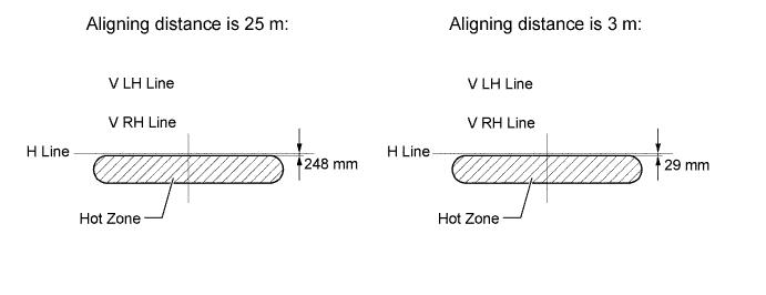
except China and Taiwan:
Turn on the fog light and check if the cutoff line falls within the specified area in the following illustration.
Tech Tips
-
If the alignment distance is 25 m (82 ft.):
The upper edge of the hot zone for the fog light should be 248 mm (9.76 in.) below the H line.
-
If the alignment distance is 3 m (9.84 ft.):
The upper edge of the hot zone for the fog light should be 29 mm (1.14 in.) below the H line.
-
-
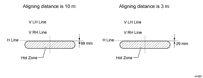
for China and Taiwan:
Turn on the fog light and check if the cutoff line falls within the specified area in the following illustration.
Tech Tips
-
If the alignment distance is 10 m (32.8 ft.):
The upper edge of the hot zone for the fog light should be 99 mm (3.89 in.) below the H line.
-
If the alignment distance is 3 m (9.84 ft.):
The upper edge of the hot zone for the fog light should be 29 mm (1.14 in.) below the H line.
-
-
-
ADJUST FOG LIGHT AIMING
-
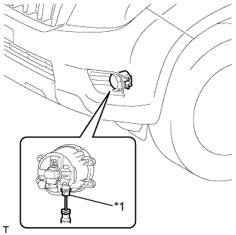
Text in Illustration *1 Aiming Screw Adjust the aim vertically.
Adjust the aim of each fog light to the specified range by turning the aiming screw with a screwdriver.
Note
The final turn of the aiming screw should be made in the clockwise direction. If the screw is tightened excessively, loosen it, and then retighten it so that the final turn of the screw is in the clockwise direction.
Tech Tips
If it is not possible to correctly adjust fog light aim, check the bulb, fog light unit and fog light unit reflector installation.
-