NAVIGATION SYSTEM (for HDD) Parking Brake Switch Circuit
DESCRIPTION
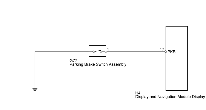
This circuit includes the parking brake switch and the display and navigation module display.
WIRING DIAGRAM
INSPECTION PROCEDURE
PROCEDURE
-
CHECK PARKING BRAKE SWITCH ASSEMBLY (DISPLAY CHECK MODE)
-
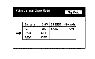
Enter the "Display Check" mode and select "Vehicle Signal Check" Click here.
-
Check that the display changes between ON and OFF according to the parking brake operation.
OK Parking Brake Condition Display Applied ON Released OFF Tech Tips
This display is updated once per second. As a result, it is normal for the display to lag behind the actual parking brake operation.
NG 
CHECK HARNESS AND CONNECTOR (DISPLAY AND NAVIGATION MODULE DISPLAY - PARKING BRAKE SWITCH) Click here
OK 
PROCEED TO NEXT SUSPECTED AREA SHOWN IN PROBLEM SYMPTOMS TABLE Click here
-
-
CHECK HARNESS AND CONNECTOR (DISPLAY AND NAVIGATION MODULE DISPLAY - PARKING BRAKE SWITCH)
-
Disconnect the H4 display and navigation module display connector.
-
Disconnect the G77 parking brake switch assembly connector.
-
Measure the resistance according to the value(s) in the table below.
Standard Resistance Tester Connection Condition Specified Condition H4-17 (PKB) - G77-1 Always Below 1 Ω H4-17 (PKB) - Body ground Always 10 kΩ or higher
NG 
REPAIR OR REPLACE HARNESS OR CONNECTOR
OK 
-
-
INSPECT PARKING BRAKE SWITCH ASSEMBLY
-
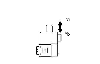
Text in Illustration *a Released *b Pushed in Remove the parking brake switch assembly Click here.
-
Measure the resistance according to the value(s) in the table below.
Standard Resistance Tester Connection Switch Condition Specified Condition 1 - Body ground Parking brake switch on (Switch pin released) Below 1 Ω Parking brake switch off (Switch pin pushed in) 10 kΩ or higher
NG
REPLACE PARKING BRAKE SWITCH ASSEMBLY Click here
OK
PROCEED TO NEXT SUSPECTED AREA SHOWN IN PROBLEM SYMPTOMS TABLE Click here
-