NAVIGATION SYSTEM (for DVD), Diagnostic DTC:B15C2

| DTC Code | DTC Name |
|---|---|
| B15C2 | Speed Signal Malfunction |
DESCRIPTION
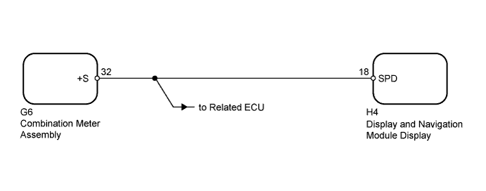
The display and navigation module display receives a vehicle speed signal from the combination meter assembly and information about the navigation antenna, and then adjusts the vehicle position.
The display and navigation module display stores this DTC when the difference between the speed information that the navigation antenna receives and the SPD pulse received from the combination meter assembly becomes large.
Tech Tips
-
A voltage of 12 V or 5 V is output from each ECU and then input to the combination meter assembly. This signal is changed to a pulse signal at the transistor in the combination meter assembly. Each ECU controls its respective systems based on the pulse signal.
-
If a short occurs in any of the ECUs or in a wire harness connected to an ECU, all systems related to the components in the diagram below will not operate normally.
| DTC Code | DTC Detection Condition | Trouble Area |
|---|---|---|
| B15C2 | A difference between the GPS speed and SPD pulse is detected. |
|
WIRING DIAGRAM
INSPECTION PROCEDURE
PROCEDURE
-
CHECK VEHICLE SENSOR
-
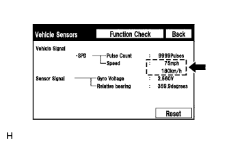
Enter "GPS & Vehicle Sensor" (Vehicle Sensors) Click here.
-
While driving the vehicle, compare the "SPD" indicator to the reading on the speedometer. Check if these readings are equal or almost equal.
OK The readings are equal or almost equal.
NG 
GO TO METER / GAUGE SYSTEM Click here
OK 
REPLACE DISPLAY AND NAVIGATION MODULE DISPLAY Click here
-