INSTRUMENT PANEL SPEAKER INSTALLATION

Tech Tips
-
Use the same procedure for the RH and LH sides.
-
The procedure listed below is for the LH side.
-
A bolt without a torque specification is shown in the standard bolt chart Click here.
-
INSTALL FRONT NO. 4 SPEAKER ASSEMBLY
-
Connect the speaker connector.
-
Align the speaker with the positioning pins of the instrument panel and temporarily install the speaker.
-
Install the front No. 4 speaker with the 2 bolts.
Note
-
Do not touch the cone of the speaker.
-
When installing the speaker to the instrument panel, be careful that the wires do not get caught between parts.
-
-
-
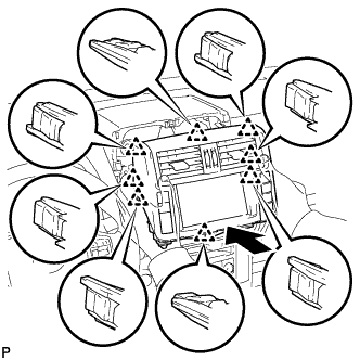
INSTALL UPPER INSTRUMENT CLUSTER FINISH PANEL
-
Attach the 8 clips and 2 guides to install the upper instrument cluster finish panel.
-
-
INSTALL DISPLAY AND NAVIGATION MODULE DISPLAY WITH BRACKET (w/ Navigation System)
-
Connect the connectors.
-
Insert the display and navigation module display and attach the 8 clips on the backside of the display and navigation module display.
Note
When inserting the display, do not press the knobs on it.
-
Install the display and navigation module display with the 4 bolts.
- Torque:
- 12.5 N*m { 127 kgf*cm, 9 ft.*lbf }
-
-
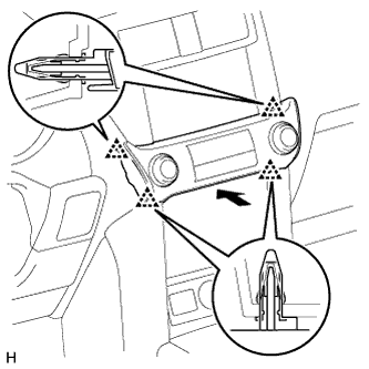
INSTALL INTEGRATION CONTROL AND PANEL ASSEMBLY
-
Connect the connector.
-
Attach the 4 clips to install the integration control and panel assembly.
-
-
INSTALL FRONT NO. 2 SPEAKER ASSEMBLY
-
Connect the connector.
-
Align the speaker with the positioning pins of the instrument panel and temporarily install the speaker.
-
Install the front No. 2 speaker with the 2 bolts.
Note
-
Do not touch the cone of the speaker.
-
When installing the speaker to the instrument panel, be careful that the wires do not get caught between parts.
-
-
-
INSTALL NO. 1 INSTRUMENT PANEL SPEAKER PANEL SUB-ASSEMBLY
-
Attach the 2 clips, claw and 2 guides to install the No. 1 instrument panel speaker panel.
-
-
INSTALL FRONT PILLAR GARNISH LH
-
Attach the 3 guides to install the front pillar garnish.
-
-
INSTALL NO. 1 ASSIST GRIP
Tech Tips
Use the same procedure for the other No. 1 assist grip.
-
Attach the 2 claws to install the No. 1 assist grip.
-
Install the 2 bolts.
-
-
REMOVE FRONT NO. 1 ASSIST GRIP PLUG LH
Tech Tips
Use the same procedure for the other front No. 1 assist grip plug.
-
Attach the 2 claws to install the front No. 1 assist grip plug.
-
-
CONNECT CABLE TO NEGATIVE BATTERY TERMINAL
Note
When disconnecting the cable, some systems need to be initialized after the cable is reconnected Click here.