INSTRUMENT PANEL SPEAKER REMOVAL

Tech Tips
-
Use the same procedure for the RH and LH sides.
-
The procedure listed below is for the LH side.
-
DISCONNECT CABLE FROM NEGATIVE BATTERY TERMINAL
Note
-
After turning the ignition switch off, waiting time may be required before disconnecting the cable from the battery terminal. Therefore, make sure to read the disconnecting the cable from the battery terminal notice before proceeding with work. Click here
-
When disconnecting the cable, some systems need to be initialized after the cable is reconnected Click here.
-
-
REMOVE FRONT NO. 1 ASSIST GRIP PLUG LH
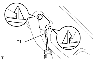
Text in Illustration *1 Protective Tape Tech Tips
Use the same procedure for the other front No. 1 assist grip plug.
-
Using a screwdriver, detach the 2 claws and remove the front No. 1 assist grip plug.
Tech Tips
Tape the screwdriver tip before use.
-
-
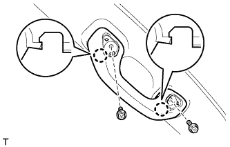
REMOVE NO. 1 ASSIST GRIP
Tech Tips
Use the same procedure for the other No. 1 assist grip.
-
Remove the 2 bolts.
-
Detach the 2 claws and remove the No. 1 assist grip.
-
-
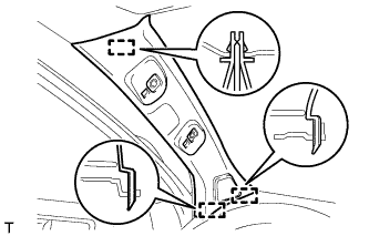
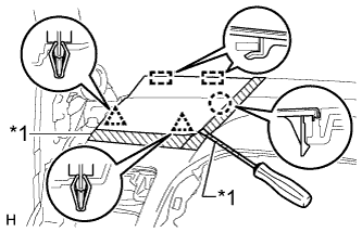
REMOVE FRONT PILLAR GARNISH LH
-
Detach the 3 guides and remove the front pillar garnish.
-
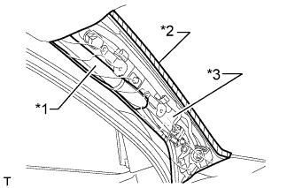
Text in Illustration *1 Curtain Shield Airbag Assembly *2 Adhesive Tape *3 Protective Cover w/ Curtain Shield Airbag:
Protect the curtain shield airbag assembly.
-
Completely cover the airbag with a cloth or nylon sheet and secure the ends of the cover with adhesive tape as shown in the illustration.
Note
Cover the curtain shield airbag with a protective cover as soon as the front pillar garnish is removed.
-
-
-
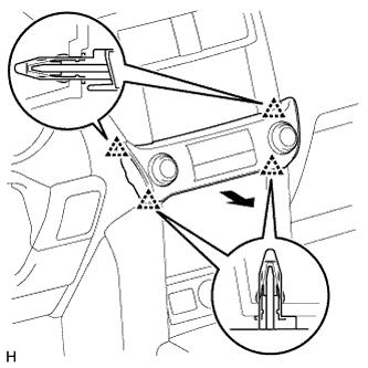
REMOVE NO. 1 INSTRUMENT PANEL SPEAKER PANEL SUB-ASSEMBLY
Text in Illustration *1 Protective Tape
-
Put protective tape around the No. 1 instrument panel speaker panel.
-
Using a screwdriver, detach the 2 clips, claw, and 2 guides and remove the No. 1 instrument panel speaker panel.
Tech Tips
Tape the screwdriver tip before use.
-
-
REMOVE FRONT NO. 2 SPEAKER ASSEMBLY
-
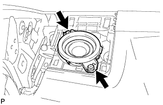
Remove the 2 bolts.
-
Remove the front No. 2 speaker and disconnect the speaker connector.
Note
Do not touch the cone of the speaker.
-
-
REMOVE INTEGRATION CONTROL AND PANEL ASSEMBLY
-
Detach the 4 clips.
-
Disconnect the connector and remove the integration control and panel assembly.
-
-
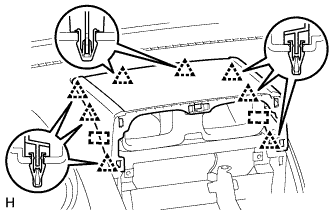
REMOVE DISPLAY AND NAVIGATION MODULE DISPLAY WITH BRACKET (w/ Navigation System)
-
Remove the 4 bolts.
-
Pull the display and navigation module display to detach the 8 clips on the backside of the display and navigation module display.
-
Disconnect the connectors and remove the display and navigation module display.
-
-
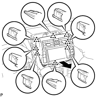
REMOVE UPPER INSTRUMENT CLUSTER FINISH PANEL
-
Detach the 8 clips and 2 guides and remove the upper instrument cluster finish panel.
-
-
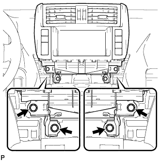
REMOVE FRONT NO. 4 SPEAKER ASSEMBLY
-
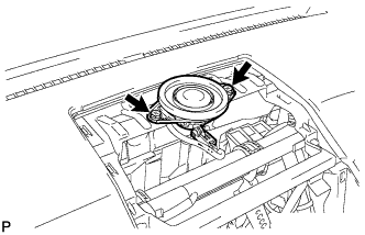
Remove the 2 bolts.
-
Remove the front No. 4 speaker and disconnect the speaker connector.
Note
Do not touch the cone of the speaker.
-