FRONT DOOR SPEAKER REMOVAL

Tech Tips
-
Use the same procedure for the RH and LH sides.
-
The procedure listed below is for the LH side.
-
DISCONNECT CABLE FROM NEGATIVE BATTERY TERMINAL
Note
-
After turning the ignition switch off, waiting time may be required before disconnecting the cable from the battery terminal. Therefore, make sure to read the disconnecting the cable from the battery terminal notice before proceeding with work. Click here
-
When disconnecting the cable, some systems need to be initialized after the cable is reconnected Click here.
-
-
REMOVE FRONT DOOR LOWER FRAME BRACKET GARNISH LH
-
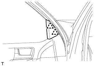
Detach the 2 clips and remove the front door lower frame bracket garnish LH.
-
-
REMOVE NO. 2 DOOR INSIDE HANDLE BEZEL LH
-
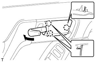
Using a moulding remover, detach the 3 claws and remove the inside handle bezel as shown in the illustration.
-
-
REMOVE ASSIST GRIP COVER LH
-
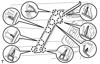
Using moulding remover A, detach the 8 claws and remove the assist grip cover.
-
-
REMOVE FRONT DOOR TRIM BOARD SUB-ASSEMBLY LH
-
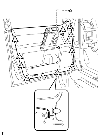
Remove the 3 screws.
-
Remove the 12 clips.
-
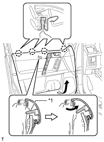
Text in Illustration *1 Reference Boss Pull out the front door trim board sub-assembly in the direction indicated by the arrow in the illustration.
-
Raise the front door trim board sub-assembly to detach the 4 claws and remove the front door trim board sub-assembly together with the front door inner glass weatherstrip LH.
-
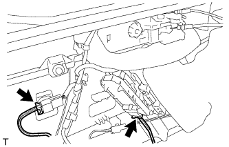
Disconnect the 2 connectors.
-
w/ Seat Position Memory System:
-
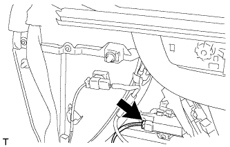
Disconnect the connectors.
-
-
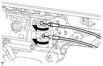
Disconnect the front door lock remote control cable assembly and front door inside locking cable assembly.
-
-
REMOVE FRONT DOOR INNER GLASS WEATHERSTRIP LH
-
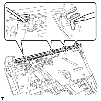
Using a screwdriver, detach the 4 claws and remove the front door inner glass weatherstrip from the front door trim board sub-assembly as shown in the illustration.
-
-
REMOVE FRONT NO. 1 SPEAKER ASSEMBLY
-
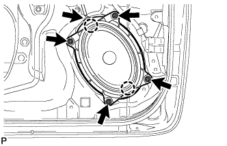
Disconnect the speaker connector.
-
Remove the 4 screws.
-
Detach the 2 claws and remove the speaker.
Note
Do not touch the cone of the speaker.
-