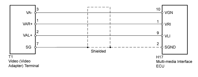
REAR SEAT ENTERTAINMENT SYSTEM Sound Signal Circuit between Multi-media Interface ECU and Video Terminal
DESCRIPTION
This is the sound signal circuit from the video terminal to the multi-media interface ECU.
WIRING DIAGRAM
INSPECTION PROCEDURE
PROCEDURE
-
CHECK HARNESS AND CONNECTOR (MULTI-MEDIA INTERFACE ECU - VIDEO TERMINAL)
-
Disconnect the H17 multi-media interface ECU connector.
-
Disconnect the T1 video (video adapter) terminal connector.
-
Measure the resistance according to the value(s) in the table below.
Standard Resistance Tester Connection Condition Specified Condition H17-10 (VGN) - T1-3 (VA-) Always Below 1 Ω H17-1 (VRI) - T1-1 (VAR+) Always Below 1 Ω H17-9 (VLI) - T1-2 (VAL+) Always Below 1 Ω H17-2 (SGND) - T1-7 (SG) Always Below 1 Ω H17-10 (VGN) - Body ground Always 10 kΩ or higher H17-1 (VRI) - Body ground Always 10 kΩ or higher H17-9 (VLI) - Body ground Always 10 kΩ or higher H17-2 (SGND) - Body ground Always 10 kΩ or higher
NG 
REPAIR OR REPLACE HARNESS OR CONNECTOR
OK 
-
-
CHECK VIDEO (VIDEO ADAPTER) TERMINAL
-
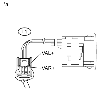
Text in Illustration *a Component with harness connected
(Video [Video Adapter] Terminal)
Using an oscilloscope, check the waveform between each terminal and the body ground according to the conditions as shown in the table below.
Standard Tester Connection Condition Specified Condition T1-1 (VAR+) - Body ground External device playing Waveform synchronized with sound is output T1-2 (VAL+) - Body ground
NG
REPLACE VIDEO (VIDEO ADAPTER) TERMINAL
OK 
PROCEED TO NEXT SUSPECTED AREA SHOWN IN PROBLEM SYMPTOMS TABLE Click here
-