AUDIO AND VISUAL SYSTEM (w/o Navigation System) Speaker Circuit (Built-in Amplifier)
DESCRIPTION
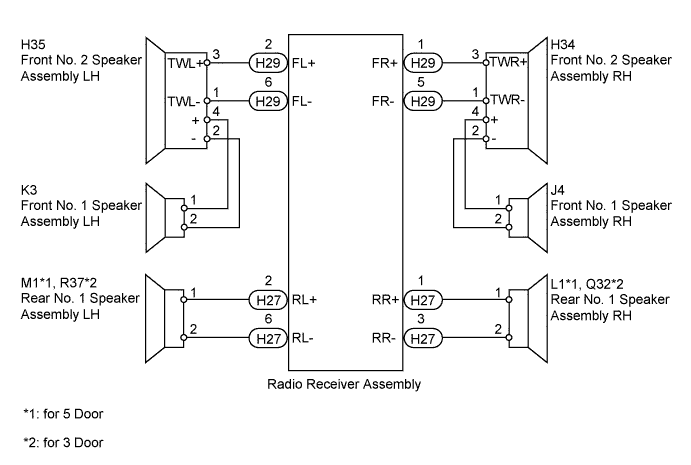
The radio receiver assembly sends sound signals to the speaker.
WIRING DIAGRAM
INSPECTION PROCEDURE
PROCEDURE
-
CHECK SPEAKER
-
Check the malfunctioning speakers.
Result Result Proceed to Malfunction in front speaker area A Malfunction in rear speaker area B
B 
INSPECT REAR NO. 1 SPEAKER ASSEMBLY Click here
A 
-
-
CHECK FRONT SIDE SPEAKER
-
Check the malfunctioning speakers.
Result Result Proceed to Front No. 1 speaker assembly A Front No. 2 speaker assembly B
B
INSPECT FRONT NO. 2 SPEAKER ASSEMBLY Click here
A
-
-
INSPECT FRONT NO. 1 SPEAKER ASSEMBLY
-
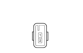
Disconnect the J4*1 and/or K3*2 front No. 1 speaker assembly connector.
-
*1: for RH
-
*2: for LH
-
-
Measure the resistance according to the value(s) in the table below.
Standard Resistance Tester Connection Condition Specified Condition 1 - 2 Always 4.0 Ω
NG 
REPLACE FRONT NO. 1 SPEAKER ASSEMBLY Click here
OK
-
-
CHECK HARNESS AND CONNECTOR (FRONT NO. 2 SPEAKER - FRONT NO. 1 SPEAKER)
-
*1: for RH
-
*2: for LH
-
Disconnect the J4*1 and/or K3*2 front No. 1 speaker assembly connector.
-
Disconnect the H34*1 and/or H35*2 front No. 2 speaker assembly connector.
-
Measure the resistance according to the value(s) in the table below.
Standard Resistance for RH Tester Connection Condition Specified Condition J4-1- H34-4 (+) Always Below 1 Ω J4-2 - H34-2 (-) Always Below 1 Ω J4-1 - Body ground Always 10 kΩ or higher J4-2 - Body ground Always 10 kΩ or higher for LH Tester Connection Condition Specified Condition K3-1 - H35-4 (+) Always Below 1 Ω K3-2 - H35-2 (-) Always Below 1 Ω K3-1 - Body ground Always 10 kΩ or higher K3-2 - Body ground Always 10 kΩ or higher
NG
REPAIR OR REPLACE HARNESS OR CONNECTOR
OK
-
-
INSPECT FRONT NO. 2 SPEAKER ASSEMBLY
-
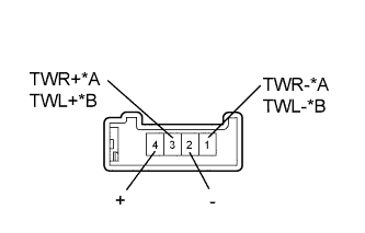
Text in Illustration *A for RH *B for LH Disconnect the H34*1 and/or H35*2 front No. 2 speaker assembly connector.
-
*1: for RH
-
*2: for LH
-
-
Measure the resistance according to the value(s) in the table below.
Standard Resistance for RH Tester Connection Condition Specified Condition 3 (TWR+) - 4 (+) Always Below 1 Ω 1 (TWR-) - 2 (-) Always Below 1 Ω for LH Tester Connection Condition Specified Condition 3 (TWL+) - 4 (+) Always Below 1 Ω 1 (TWL-) - 2 (-) Always Below 1 Ω Result Result Proceed to OK (w/o Accessory Meter) A OK (w/ Accessory Meter) B NG C
B
REPLACE RADIO RECEIVER ASSEMBLY Click here
C
REPLACE FRONT NO. 2 SPEAKER ASSEMBLY Click here
A 
REPLACE RADIO RECEIVER ASSEMBLY Click here
-
-
INSPECT FRONT NO. 2 SPEAKER ASSEMBLY
-
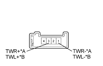
Text in Illustration *A *for RH *B *for LH Disconnect the H34*1 and/or H35*2 front No. 2 speaker assembly connector.
-
*1: for RH
-
*2: for LH
-
-
Measure the resistance according to the value(s) in the table below.
Standard Resistance for RH Tester Connection Condition Specified Condition 3 (TWR+) - 1 (TWR-) Always 4 Ω for LH Tester Connection Condition Specified Condition 3 (TWL+) - 1 (TWL-) Always 4 Ω
NG
REPLACE FRONT NO. 2 SPEAKER ASSEMBLY Click here
OK
-
-
CHECK HARNESS AND CONNECTOR (RADIO RECEIVER - FRONT NO. 2 SPEAKER)
-
Disconnect the H29 radio receiver assembly connector.
-
Disconnect the H34*1 and/or H35*2 front No. 2 speaker assembly connector.
-
*1: for RH
-
*2: for LH
-
-
Measure the resistance according to the value(s) in the table below.
Standard Resistance for RH Tester Connection Condition Specified Condition H29-1 (FR+) - H34-3 (TWR+) Always Below 1 Ω H29-5 (FR-) - H34-1 (TWR-) Always Below 1 Ω H29-1 (FR+) - Body ground Always 10 kΩ or higher H29-5 (FR-) - Body ground Always 10 kΩ or higher for LH Tester Connection Condition Specified Condition H29-2 (FL+) - H35-3 (TWL+) Always Below 1 Ω H29-6 (FL-) - H35-1 (TWL-) Always Below 1 Ω H29-2 (FL+) - Body ground Always 10 kΩ or higher H29-6 (FL-) - Body ground Always 10 kΩ or higher Result Result Proceed to OK (w/o Accessory Meter) A OK (w/ Accessory Meter) B NG C
B
REPLACE RADIO RECEIVER ASSEMBLY Click here
C
REPAIR OR REPLACE HARNESS OR CONNECTOR
A
REPLACE RADIO RECEIVER ASSEMBLY Click here
-
-
INSPECT REAR NO. 1 SPEAKER ASSEMBLY
-
for 5 Door:
-
Disconnect the L1*1 and/or M1*2 rear No. 1 speaker assembly connectors.
-
Measure the resistance according to the value(s) in the table below.
Standard Resistance Tester Connection Condition Specified Condition 1 - 2 Always 4 Ω
-
-
for 3 Door:
-
Disconnect the Q32*1 and/or R37*2 rear No. 1 speaker assembly connectors.
-
Measure the resistance according to the value(s) in the table below.
Standard Resistance Tester Connection Condition Specified Condition 1 - 2 Always 4 Ω
-
NG
REPLACE REAR NO. 1 SPEAKER ASSEMBLY Click here
OK
-
-
CHECK HARNESS AND CONNECTOR (RADIO RECEIVER - REAR NO. 1 SPEAKER)
-
*1: for RH
-
*2: for LH
-
Disconnect the H27 radio receiver assembly connector.
-
for 5 Door:
Disconnect the L1*1 and/or M1*2 rear No. 1 speaker assembly connector.
-
for 3 Door:
Disconnect the Q32*1 and/or R37*2 rear No. 1 speaker assembly connector.
-
Measure the resistance according to the value(s) in the table below.
Standard Resistance for RH Tester Connection Condition Specified Condition H27-1 (RR+) - L1-1 Always Below 1 Ω H27-3 (RR-) - L1-2 Always Below 1 Ω H27-1 (RR+) - Q32-1 Always Below 1 Ω H27-3 (RR-) - Q32-2 Always Below 1 Ω H27-1 (RR+) - Body ground Always 10 kΩ or higher H27-3 (RR-) - Body ground Always 10 kΩ or higher for LH Tester Connection Condition Specified Condition H27-2 (RL+) - M1-1 Always Below 1 Ω H27-6 (RL-) - M1-2 Always Below 1 Ω H27-2 (RL+) - R37-1 Always Below 1 Ω H27-6 (RL-) - R37-2 Always Below 1 Ω H27-2 (RL+) - Body ground Always 10 kΩ or higher H27-6 (RL-) - Body ground Always 10 kΩ or higher Result Result Proceed to OK (w/o Accessory Meter) A OK (w/ Accessory Meter) B NG C
B
REPLACE RADIO RECEIVER ASSEMBLY Click here
C
REPAIR OR REPLACE HARNESS OR CONNECTOR
A
REPLACE RADIO RECEIVER ASSEMBLY Click here
-