AUDIO AND VISUAL SYSTEM (w/o Navigation System) Illumination Circuit
DESCRIPTION
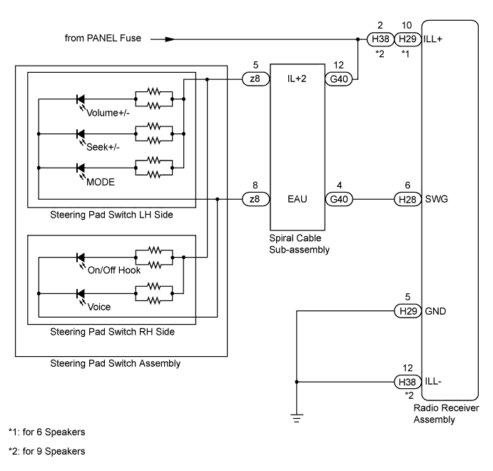
Power is supplied to the radio receiver assembly and steering pad switch illumination when the light control switch is in the TAIL or HEAD position.
WIRING DIAGRAM
INSPECTION PROCEDURE
CAUTION:
The vehicle is equipped with an SRS (Supplemental Restraint System) which includes components such as airbags. Before servicing (including removal or installation of parts), be sure to read the Precaution in the SRS Click here.
PROCEDURE
-
CHECK ILLUMINATION
-
Check if the illumination for the radio receiver assembly, steering pad switch, glove box or other parts (hazard switch, transmission control switch, etc.) come on when the light control switch is turned to the HEAD or TAIL position.
Result Result Proceed to Illumination comes on for all components except steering pad switch. A Illumination comes on for all components except radio receiver assembly. B No illumination comes on (radio receiver, hazard switch, glove box, etc.). C Illumination comes on for all components except steering pad switch and radio receiver assembly. D
B 
CHECK HARNESS AND CONNECTOR (RADIO RECEIVER - BATTERY) Click here
C 
GO TO LIGHTING SYSTEM Click here
D
CHECK HARNESS AND CONNECTOR (RADIO RECEIVER - BODY GROUND) Click here
A 
-
-
CHECK HARNESS AND CONNECTOR (SPIRAL CABLE - BATTERY)
-
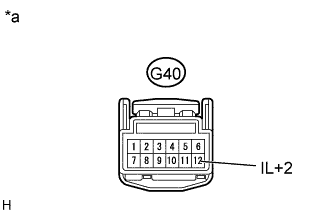
Text in Illustration *a Front view of wire harness connector
(to Spiral Cable Sub-assembly)
Disconnect the G40 spiral cable sub-assembly connector.
-
Measure the voltage according to the value(s) in the table below.
Standard Voltage Tester Connection Switch Condition Specified Condition G40-12 (IL+2) - Body ground Light control switch TAIL or HEAD 11 to 14 V
NG
REPAIR OR REPLACE HARNESS OR CONNECTOR
OK
-
-
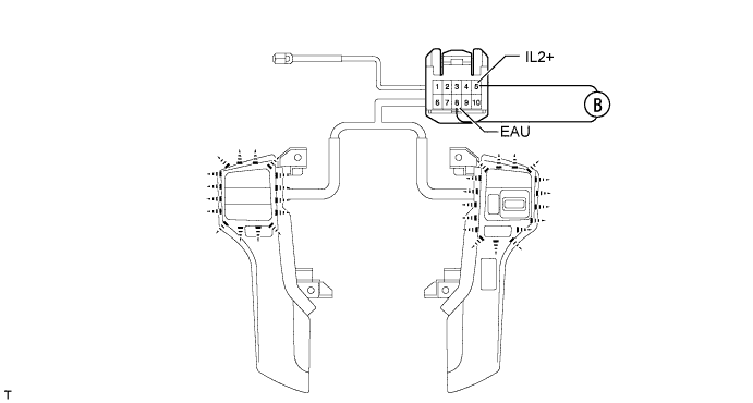
INSPECT STEERING PAD SWITCH ASSEMBLY
-
Remove the steering pad switch assembly connector Click here.
-
Connect the positive (+) lead of the battery to terminal 5 (IL+2) and the negative (-) lead of the battery to terminal 8 (EAU) of the steering pad switch assembly connector.
-
Check if the illumination for the steering pad switch assembly comes on.
OK Illumination for the steering pad switch assembly comes on.
NG
REPLACE STEERING PAD SWITCH ASSEMBLY Click here
OK
-
-
INSPECT SPIRAL CABLE SUB-ASSEMBLY
-
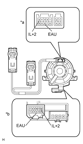
Text in Illustration *a Steering Pad Switch Assembly Side *b Vehicle Side Remove the spiral cable sub-assembly Click here.
-
Measure the resistance according to the value(s) in the table below.
Standard Resistance Tester Connection Condition Specified Condition 8 (EAU) - 4 (EAU) Spiral cable is turned 2.5 rotations counterclockwise Below 1 Ω Spiral cable is centered Spiral cable is turned 2.5 rotations clockwise 5 (IL+2) - 12 (IL+2) Spiral cable is turned 2.5 rotations counterclockwise Spiral cable is centered Spiral cable is turned 2.5 rotations clockwise CAUTION:
The spiral cable is an important part of the SRS airbag system. Incorrect removal or installation of the spiral cable may prevent the airbag from deploying. Be sure to read Precaution in the SRS Click here.
NG
REPLACE SPIRAL CABLE SUB-ASSEMBLY Click here
OK
-
-
CHECK HARNESS AND CONNECTOR (RADIO RECEIVER - SPIRAL CABLE)
-
Disconnect the H28 radio receiver assembly connector.
-
Disconnect the G40 spiral cable sub-assembly connector.
-
Measure the resistance according to the value(s) in the table below.
Standard Resistance Tester Connection Condition Specified Condition H28-6 (SWG) - G40-4 (EAU) Always Below 1 Ω H28-6 (SWG) - Body ground Always 10 kΩ or higher
NG
REPAIR OR REPLACE HARNESS OR CONNECTOR
OK 
PROCEED TO NEXT SUSPECTED AREA SHOWN IN PROBLEM SYMPTOMS TABLE Click here
-
-
CHECK HARNESS AND CONNECTOR (RADIO RECEIVER - BATTERY)
-
for 6 Speakers:
-
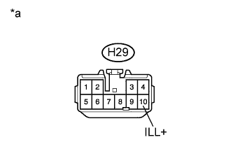
Text in Illustration *a Front view of wire harness connector
(to Radio Receiver Assembly)
Disconnect the H29 radio receiver assembly connector.
-
Measure the voltage according to the value(s) in the table below.
Standard Voltage Tester Connection Switch Condition Specified Condition H29-10 (ILL+) - Body ground Light control switch TAIL or HEAD 11 to 14 V
-
-
for 9 Speakers:
-
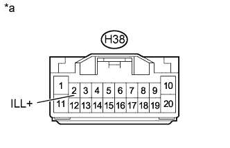
Text in Illustration *a Front view of wire harness connector
(to Radio Receiver Assembly)
Disconnect the H38 radio receiver assembly connector.
-
Measure the voltage according to the value(s) in the table below.
Standard Voltage Tester Connection Switch Condition Specified Condition H38-2 (ILL+) - Body ground Light control switch TAIL or HEAD 11 to 14 V
-
NG
REPAIR OR REPLACE HARNESS OR CONNECTOR
OK
PROCEED TO NEXT SUSPECTED AREA SHOWN IN PROBLEM SYMPTOMS TABLE Click here
-
-
CHECK HARNESS AND CONNECTOR (RADIO RECEIVER - BODY GROUND)
-
for 6 Speakers:
-
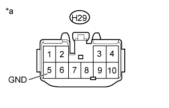
Text in Illustration *a Front view of wire harness connector
(to Radio Receiver Assembly)
Disconnect the H29 radio receiver assembly connector.
-
Measure the resistance according to the value(s) in the table below.
Standard Resistance Tester Connection Condition Specified Condition H29-5 (GND) - Body ground Always Below 1 Ω
-
-
for 9 Speakers:
-
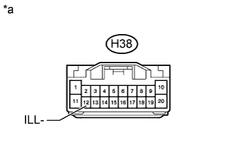
Text in Illustration *a Front view of wire harness connector
(to Radio Receiver Assembly)
Disconnect the H38 radio receiver assembly connector.
-
Measure the resistance according to the value(s) in the table below.
Standard Resistance Tester Connection Condition Specified Condition H38-12 (ILL-) - Body ground Always Below 1 Ω
-
NG
REPAIR OR REPLACE HARNESS OR CONNECTOR
OK
PROCEED TO NEXT SUSPECTED AREA SHOWN IN PROBLEM SYMPTOMS TABLE Click here
-