AUDIO AND VISUAL SYSTEM (w/o Navigation System) DTC CHECK / CLEAR

Tech Tips
If the system cannot enter the diagnostic mode, inspect the AVC-LAN and all the components that are connected to the AVC-LAN for short circuits and repair or replace the malfunctioning part Click here.
-
STARTING DIAGNOSTIC MODE
-
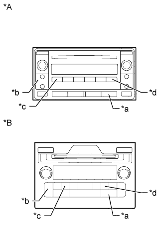
Text in Illustration *A w/o Accessory Meter *B w/ Accessory Meter *a AUX, DISC-AUX or CD-AUX *b Seek Track *c Channel 1 *d Channel 6 Turn the ignition switch to ACC.
-
Turn off the audio system.
-
While pressing the preset switches "channel 1" and "channel 6" at the same time, press the "AUX" switch 3 times.
Tech Tips
-
A beep is emitted 3 times and the diagnostic function is activated. The system enters the all element illumination mode and the switch check mode.
-
The layout of the switches in the illustration is only an example and may differ depending on the vehicle.
-
-
-
ALL ELEMENT ILLUMINATION MODE AND SWITCH CHECK MODE
Tech Tips
The illumination status of all switches and operations of the panel switches can be checked.
-
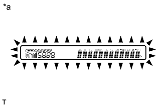
Text in Illustration *a Example Check that all elements are on.
-
When pressing each panel switch, check that a beep is emitted.
Note
Pressing the "SEEK TRACK UP" switch transfers the screen to the stereo jack adapter connection check screen. Check the operation of this switch by confirming the transfer of the screen.
-
-
STEREO JACK ADAPTER CONNECTION CHECK MODE
-
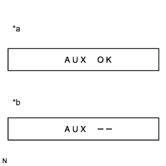
Text in Illustration *a When a stereo jack adapter is connected *b When a stereo jack adapter is not connected Press the "SEEK TRACK UP" switch.
-
Check if the stereo jack adapter is recognized.
Tech Tips
-
The radio receiver displays "AUX OK" or "AUX ON" when it recognizes a connection to the stereo jack adapter.
-
Vehicles that do not have a stereo jack adapter also have this function.
-
This function is not to check connection status to an external device, but to check recognition of the stereo jack adapter.
-
-
-
SERVICE CHECK MODE
-
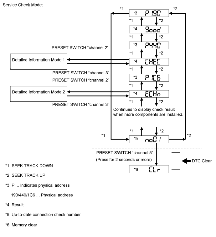
Press the "SEEK TRACK UP" switch.
Tech Tips
For details of the service check mode, refer to "Check DTC" and "DTC Clear/Recheck".
-
-
FINISHING DIAGNOSTIC MODE
-
Press the "AUX" switch for 2 seconds or more, or turn the ignition switch off.
-
-
CHECK DTC
Tech Tips
Illustrations may differ from the actual vehicle depending on the device settings and options. Therefore, some detailed areas may not be exactly the same as on the actual vehicle.
-
Reference:
In the system check mode, the system check and the diagnostic memory check are performed, and the check results are displayed in ascending order of the component codes (physical address).
Term Meaning Component code
(Physical address)
Three-digit code (in hexadecimal) given to each device comprising AVC-LAN. Corresponding to its function, individual symbol is provided. Logical address Two-digit code (in hexadecimal) given to each function of each device comprising AVC-LAN. -
Service check result display
Display Original word Meaning Action to be Taken good Good (normal) No DTCs are stored in both "System Check Mode" and "Diagnostic Memory Mode". - nCon No connection The system recognized the component when it was registered, but the component gives no response to "Diagnostic Mode ON Request". Check the power source circuit and the communication circuit of the component indicated by the component code (physical address). ECHn Exchange One or more DTCs for "Exchange" are detected in either "System Check Mode" or "Diagnostic Memory Mode". Go to the detailed information mode to check the trouble area on the DTC chart. CHEC Check When no DTCs are stored for "Exchange", one or more DTCs for "Check" are stored in either "System Check Mode" or "Diagnostic Memory Mode". Go to the detailed information mode to check the trouble area on the DTC chart. OLd Old version Old DTC application is identified and DTC is stored in either "System Check Mode" or "Diagnostic Memory Mode". - nrES No response The device gives no response to any one of "System Check Mode ON Request", "System Check Result Request", and "Diagnostic Memory Request". Check the power source circuit and the communication circuit of the component indicated by the component code (physical address). -
Device name and physical address
Physical Address No. Name 190 Radio receiver assembly 19D "Bluetooth" handsfree module 388 Multi-media interface ECU -
Service check mode
-
Press the "SEEK TRACK" switch to see the check result of each component.
-
The component code (physical address) is displayed first, and then the check result follows.
Tech Tips
-
If all check results are "good", the system judges that no DTC exists.
-
If the preset switch "channel 1" is pressed in the service check mode, service check is performed again.
-
This illustration is only an example and may differ in cases such as for each option part and output DTCs.
-
-
-
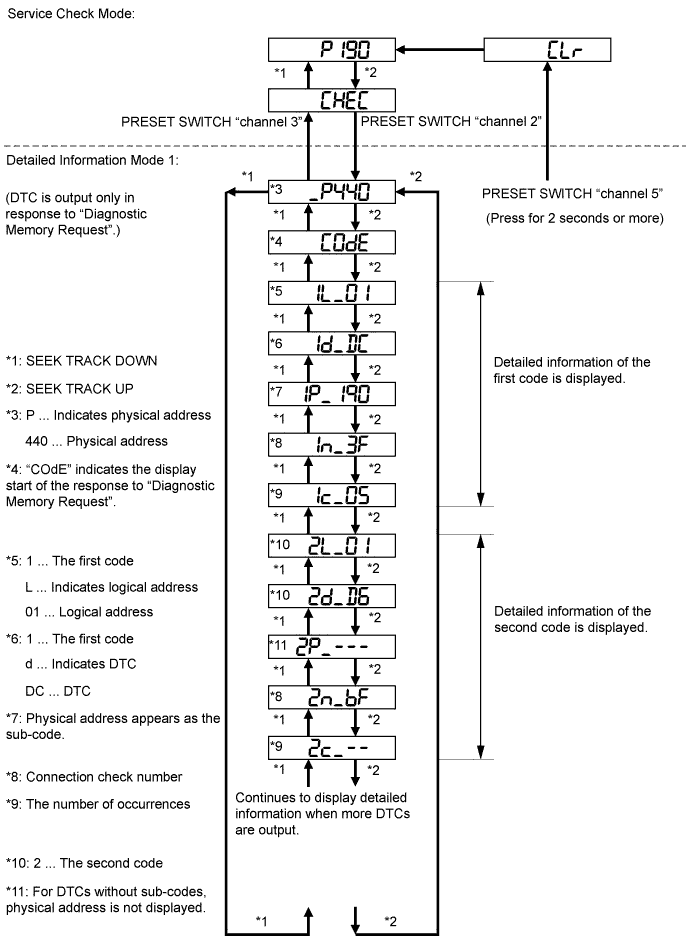
Detailed information mode 1
Tech Tips
-
"Detailed Information Mode 1" is displayed when there is no response to "System Check Result Request" and DTC is stored only in "Diagnostic Memory Request".
-
The component device code (physical address) is displayed first, and then the check result follows.
-
This illustration is only an example and may differ in cases such as for each option part and output DTCs.
-
Press the preset switch "channel 2" to go to the "Detailed Information Mode 1".
-
Press the "SEEK TRACK" switch to display the physical address and DTC of the component.
-
Press the preset switch "channel 3" to go to the "Service Check Mode".
-
It is necessary to distinguish between the displays of the responses to "System Check Result Request" and "Diagnostic Memory Request". In order to distinguish between the information detected in "System Check Mode" and "Diagnostic Memory Mode" in "ECHn", "CHEC", and "OLd" in "Detailed Information Mode 1", refer to the following:
-
"SyS" is displayed before the detailed codes (detected as a result of "System Check Result Request") are displayed.
-
"COdE" is displayed before the detailed codes (detected as a result of "Diagnostic Memory Request") are displayed.
Tech Tips
-
The response to "System Check Result Request" is the current information given from each ECU as a result of the system check.
-
The response to "Diagnostic Memory Request" contains the information received from each ECU or stored in each ECU in the past.
-
The response to "Diagnostic Memory Request" is the output DTCs as a result of the diagnostic memory check or the DTCs received from each ECU.
-
"System Check Result Request (SyS)" is displayed first, and then the logical address and DTC appear in order.
-
"Diagnostic Memory Request (COdE)" is displayed first, and then the logical address, DTC, sub-code, connection check number, and the number of occurrences appear in order.
-
-
-
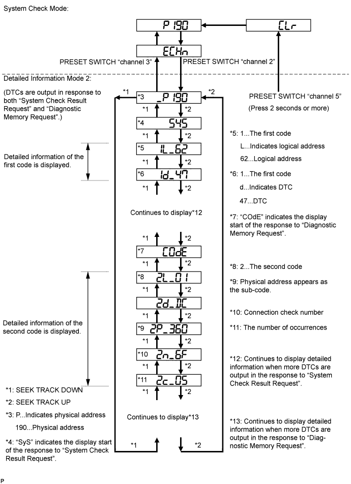
Detailed information mode 2
Tech Tips
-
"Detailed Information Mode 2" is displayed when DTCs are stored in the responses to both "System Check Result Request" and "Diagnostic Memory Request".
-
The component device code (physical address) is displayed first, and then the check result follows.
-
This illustration is only an example and may differ in cases such as for each option part and output DTCs.
-
Press the preset switch "channel 2" to go to the "Detailed Information Mode 2".
-
Press the "SEEK TRACK" switch to display the physical address and DTC of the component.
-
Press the preset switch "channel 3" to go to the "Service Check Mode".
-
It is necessary to distinguish between the displays of the responses to "System Check Result Request" and "Diagnostic Memory Request". In order to distinguish between the information detected in "System Check Mode" and "Diagnostic Memory Mode" in "ECHn", "CHEC", and "OLd" in "Detailed Information Mode 2", refer to the following:
-
"SyS" is displayed before the detailed codes (detected as a result of "System Check Result Request") are displayed.
-
"COdE" is displayed before the detailed codes (detected as a result of "Diagnostic Memory Request") are displayed.
Tech Tips
-
The response to "System Check Result Request" is the current information given from each ECU as a result of the system check.
-
The response to "Diagnostic Memory Request" contains the information received from each ECU or stored in each ECU in the past.
-
The response to "Diagnostic Memory Request" is the output DTCs as a result of the diagnostic memory check or the DTCs received from each ECU.
-
"System Check Result Request (SyS)" is displayed first, and then the logical address and DTC appear in order.
-
"Diagnostic Memory Request (COdE)" is displayed first, and then the logical address, DTC, sub-code, connection check number, and the number of occurrences appear in order.
-
-
-
-
-
DTC CLEAR/RECHECK
-
Text in Illustration *A for 6 Speakers without Accessory Meter *B for 9 Speakers with Accessory Meter *a AUX, DISC-AUX or CD-AUX *b Seek Track *c Channel 1 *d Channel 6 Clearing All DTC Memory (when clearing all the memory of the DTCs previously detected)
Tech Tips
The layout of the switches in the illustration is only an example and may differ depending on the vehicle.
-
When the preset switch "channel 5" is pressed for 2 seconds or more during "Service Check Mode", the DTCs for all components are cleared ("CLr" is displayed at this time).
Tech Tips
-
A beep sound is emitted once when the DTC memory is completely cleared.
-
When the DTC memory for all the components is cleared, only the component codes (physical address) are displayed.
-
After the DTC memory is cleared, the "Service Check Mode" is restored.
-
-
-
Clearing Individual DTC Memory (when clearing the memory of the DTC previously detected individually)
-
When the preset switch "channel 5" is pressed for 2 seconds or more during "Detailed Information Mode 1" or "Detailed Information Mode 2", the DTCs for the target component are cleared.
Tech Tips
-
A beep sound is emitted once when the DTC memory is completely cleared.
-
When the DTC memory is cleared, only the component code (physical address) is displayed for the target component.
-
After the DTC memory is cleared, the "Service Check Mode" is restored.
-
To check DTCs, press the preset switch "channel 1" and perform the system check again.
-
-
-
Press the preset switch "channel 1" to perform the service check again, and check that no DTCs are displayed for all the component codes (physical address).
-