AUDIO AND VISUAL SYSTEM (w/ Navigation System) Speaker Circuit
DESCRIPTION
The stereo component amplifier assembly sends sound signals to the speaker.
WIRING DIAGRAM
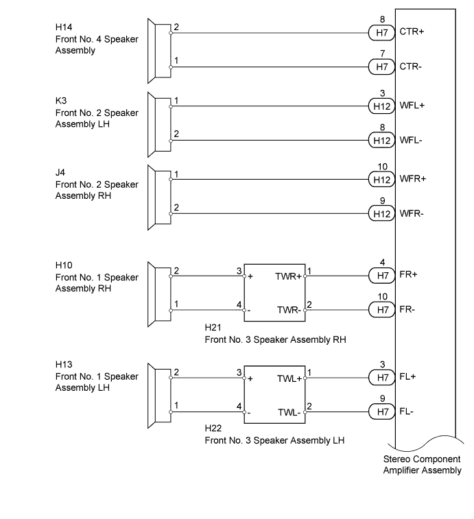
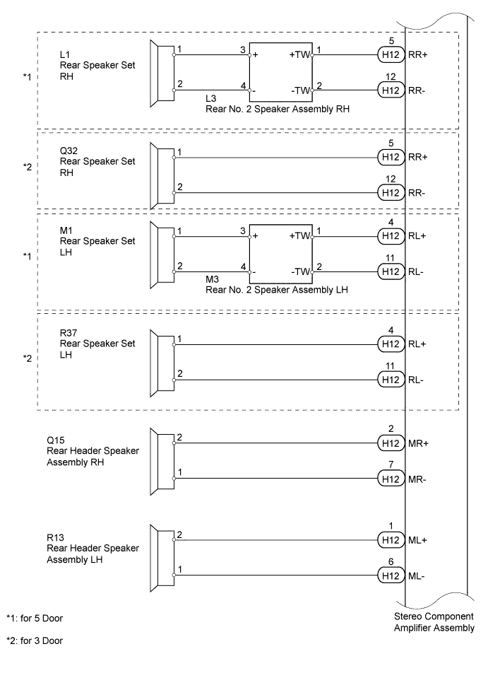
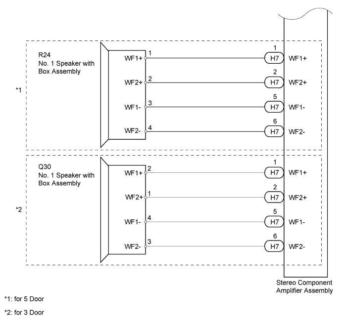
INSPECTION PROCEDURE
PROCEDURE
-
CHECK VEHICLE TYPE
-
Check the vehicle type.
Result Result Proceed to for JBL Made A for Pioneer Made B
B 
CHECK SPEAKER Click here
A 
-
-
CHECK SPEAKER
-
Check which speakers are malfunctioning.
Result Result Proceed to Malfunction in front speaker area A Malfunction in rear speaker area B All speakers do not operate C
B
CHECK REAR SIDE SPEAKER Click here
C 
REPLACE STEREO COMPONENT AMPLIFIER ASSEMBLY Click here
A
-
-
CHECK FRONT SIDE SPEAKER
-
Check which speakers are malfunctioning.
Result Result Proceed to Front No. 1 speaker assembly A Front No. 3 speaker assembly B Front No. 2 speaker assembly C Front No. 4 speaker assembly D
B
INSPECT FRONT NO. 3 SPEAKER ASSEMBLY Click here
C
INSPECT FRONT NO. 2 SPEAKER ASSEMBLY Click here
D
INSPECT FRONT NO. 4 SPEAKER ASSEMBLY Click here
A
-
-
INSPECT FRONT NO. 1 SPEAKER ASSEMBLY
-
Disconnect the H10*1 and/or H13*2 front No. 1 speaker assembly connector.
-
*1: for RH
-
*2: for LH
-
-
Measure the resistance according to the value(s) in the table below.
Standard Resistance Tester Connection Condition Specified Condition 1 - 2 Always 1.4 to 2.2 Ω
NG
REPLACE FRONT NO. 1 SPEAKER ASSEMBLY Click here
OK
-
-
CHECK HARNESS AND CONNECTOR (FRONT NO. 1 SPEAKER - FRONT NO. 3 SPEAKER)
-
*1: for RH
-
*2: for LH
-
Disconnect the H10*1 and/or H13*2 front No. 1 speaker assembly connector.
-
Disconnect the H21*1 and/or H22*2 front No. 3 speaker assembly connector.
-
Measure the resistance according to the value(s) in the table below.
Standard Resistance for RH Tester Connection Condition Specified Condition H10-1 - H21-4 (-) Always Below 1 Ω H10-2 - H21-3 (+) Always Below 1 Ω H10-1 - Body ground Always 10 kΩ or higher H10-2 - Body ground Always 10 kΩ or higher for LH Tester Connection Condition Specified Condition H13-1 - H22-4 (-) Always Below 1 Ω H13-2 - H22-3 (+) Always Below 1 Ω H13-1 - Body ground Always 10 kΩ or higher H13-2 - Body ground Always 10 kΩ or higher
NG
REPAIR OR REPLACE HARNESS OR CONNECTOR
OK
-
-
INSPECT FRONT NO. 3 SPEAKER ASSEMBLY
-
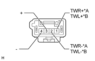
Text in Illustration *A for RH *B for LH Disconnect the H21*1 and/or H22*2 front No. 3 speaker assembly connector.
-
*1: for RH
-
*2: for LH
-
-
Measure the resistance according to the value(s) in the table below.
Standard Resistance for RH Tester Connection Condition Specified Condition 1 (TWR+) - 3 (+) Always Below 1 Ω 2 (TWR-) - 4 (-) Always Below 1 Ω for LH Tester Connection Condition Specified Condition 1 (TWL+) - 3 (+) Always Below 1 Ω 2 (TWL-) - 4 (-) Always Below 1 Ω
NG
REPLACE FRONT NO. 3 SPEAKER ASSEMBLY Click here
OK 
REPLACE STEREO COMPONENT AMPLIFIER ASSEMBLY Click here
-
-
INSPECT FRONT NO. 3 SPEAKER ASSEMBLY
-
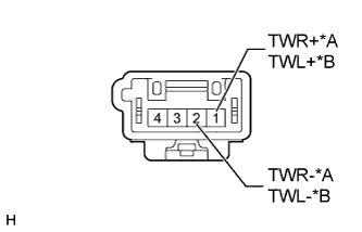
Text in Illustration *A for RH *B for LH Disconnect the H21*1 and/or H22*2 front No. 3 speaker assembly connector.
-
*1: for RH
-
*2: for LH
-
-
Measure the resistance according to the value(s) in the table below.
Standard Resistance for RH Tester Connection Condition Specified Condition 1 (TWR+) - 2 (TWR-) Always 3.4 Ω for LH Tester Connection Condition Specified Condition 1 (TWL+) - 2 (TWL-) Always 3.4 Ω
NG
REPLACE FRONT NO. 3 SPEAKER ASSEMBLY Click here
OK
-
-
CHECK HARNESS AND CONNECTOR (STEREO COMPONENT AMPLIFIER - FRONT NO. 3 SPEAKER)
-
Disconnect the H7 stereo component amplifier assembly connector.
-
Disconnect the H21*1 and/or H22*2 front No. 3 speaker assembly connector.
-
*1: for RH
-
*2: for LH
-
-
Measure the resistance according to the value(s) in the table below.
Standard Resistance for RH Tester Connection Condition Specified Condition H7-4 (FR+) - H21-1 (TWR+) Always Below 1 Ω H7-10 (FR-) - H21-2 (TWR-) Always Below 1 Ω H7-4 (FR+) - Body ground Always 10 kΩ or higher H7-10 (FR-) - Body ground Always 10 kΩ or higher for LH Tester Connection Condition Specified Condition H7-3 (FL+) - H22-1 (TWL+) Always Below 1 Ω H7-9 (FL-) - H22-2 (TWL-) Always Below 1 Ω H7-3 (FL+) - Body ground Always 10 kΩ or higher H7-9 (FL-) - Body ground Always 10 kΩ or higher
NG
REPAIR OR REPLACE HARNESS OR CONNECTOR
OK
REPLACE STEREO COMPONENT AMPLIFIER ASSEMBLY Click here
-
-
INSPECT FRONT NO. 2 SPEAKER ASSEMBLY
-
Disconnect the J4*1 and/or K3*2 front No. 2 speaker assembly connector.
-
*1: for RH
-
*2: for LH
-
-
Measure the resistance according to the value(s) in the table below.
Standard Resistance Tester Connection Condition Specified Condition 1 - 2 Always 1.6 to 2.2 Ω
NG
REPLACE FRONT NO. 2 SPEAKER ASSEMBLY Click here
OK
-
-
CHECK HARNESS AND CONNECTOR (STEREO COMPONENT AMPLIFIER - FRONT NO. 2 SPEAKER)
-
Disconnect the H12 stereo component amplifier assembly connector.
-
Disconnect the J4*1 and/or K3*2 front No. 2 speaker assembly connector.
-
*1: for RH
-
*2: for LH
Measure the resistance according to the value(s) in the table below.
Standard Resistance for RH Tester Connection Condition Specified Condition H12-10 (WFR+) - J4-1 Always Below 1 Ω H12-9 (WFR-) - J4-2 Always Below 1 Ω H12-10 (WFR+) - Body ground Always 10 kΩ or higher H12-9 (WFR-) - Body ground Always 10 kΩ or higher for LH Tester Connection Condition Specified Condition H12-3 (WFL+) - K3-1 Always Below 1 Ω H12-8 (WFL-) - K3-2 Always Below 1 Ω H12-3 (WFL+) - Body ground Always 10 kΩ or higher H12-8 (WFL-) - Body ground Always 10 kΩ or higher -
NG
REPAIR OR REPLACE HARNESS OR CONNECTOR
OK
REPLACE STEREO COMPONENT AMPLIFIER ASSEMBLY Click here
-
-
INSPECT FRONT NO. 4 SPEAKER ASSEMBLY
-
Disconnect the H14 front No. 4 speaker assembly connector.
-
Measure the resistance according to the value(s) in the table below.
Standard Resistance Tester Connection Condition Specified Condition 1 - 2 Always 1.6 to 2.2 Ω
NG
REPLACE FRONT NO. 4 SPEAKER ASSEMBLY Click here
OK
-
-
CHECK HARNESS AND CONNECTOR (STEREO COMPONENT AMPLIFIER - FRONT NO. 4 SPEAKER)
-
Disconnect the H7 stereo component amplifier assembly connector.
-
Disconnect the H14 front No. 4 speaker assembly connector.
-
Measure the resistance according to the value(s) in the table below.
Standard Resistance Tester Connection Condition Specified Condition H7-8 (CTR+) - H14-2 Always Below 1 Ω H7-7 (CTR-) - H14-1 Always Below 1 Ω H7-8 (CTR+) - Body ground Always 10 kΩ or higher H7-7 (CTR-) - Body ground Always 10 kΩ or higher
NG
REPAIR OR REPLACE HARNESS OR CONNECTOR
OK
REPLACE STEREO COMPONENT AMPLIFIER ASSEMBLY Click here
-
-
CHECK REAR SIDE SPEAKER
-
Check which speakers are malfunctioning.
Result Result Proceed to Rear speaker set A Rear No. 2 speaker assembly B Rear header speaker assembly C No. 1 speaker with box assembly D
B
INSPECT REAR NO. 2 SPEAKER ASSEMBLY Click here
C
INSPECT REAR HEADER SPEAKER ASSEMBLY Click here
D
INSPECT NO. 1 SPEAKER WITH BOX ASSEMBLY Click here
A
-
-
INSPECT REAR SPEAKER SET
-
Disconnect the L1*1 and/or M1*2 rear speaker set connector.
-
*1: for RH
-
*2: for LH
-
-
Measure the resistance according to the value(s) in the table below.
Standard Resistance Tester Connection Condition Specified Condition 1 - 2 Always 1.8 to 2.6 Ω
NG
REPLACE REAR SPEAKER SET Click here
OK
-
-
CHECK HARNESS AND CONNECTOR (REAR SPEAKER SET - REAR NO. 2 SPEAKER)
-
*1: for RH
-
*2: for LH
-
Disconnect the L1*1 and/or M1*2 rear speaker set connector.
-
Disconnect the L3*1 and/or M3*2 rear No. 2 speaker assembly connector.
-
Measure the resistance according to the value(s) in the table below.
Standard Resistance for RH Tester Connection Condition Specified Condition L1-1 - L3-3 (+) Always Below 1 Ω L1-2 - L3-4 (-) Always Below 1 Ω L1-1 - Body ground Always 10 kΩ or higher L1-2 - Body ground Always 10 kΩ or higher for LH Tester Connection Condition Specified Condition M1-1 - M3-3 (+) Always Below 1 Ω M1-2 - M3-4 (-) Always Below 1 Ω M1-1 - Body ground Always 10 kΩ or higher M1-2 - Body ground Always 10 kΩ or higher
NG
REPAIR OR REPLACE HARNESS OR CONNECTOR
OK
-
-
INSPECT REAR NO. 2 SPEAKER ASSEMBLY
-
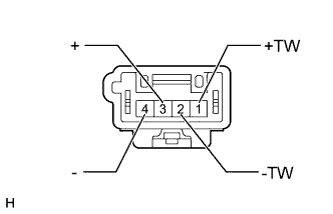
Disconnect the L3*1 and/or M3*2 rear No. 2 speaker assembly connector.
-
*1: for RH
-
*2: for LH
-
-
Measure the resistance according to the value(s) in the table below.
Standard Resistance Tester Connection Condition Specified Condition 1 (+TW) - 3 (+) Always Below 1 Ω 2 (-TW) - 4 (-) Always Below 1 Ω
NG
REPLACE REAR NO. 2 SPEAKER ASSEMBLY Click here
OK
REPLACE STEREO COMPONENT AMPLIFIER ASSEMBLY Click here
-
-
INSPECT REAR NO. 2 SPEAKER ASSEMBLY
-
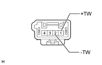
Disconnect the L3*1 and/or M3*2 rear No. 2 speaker assembly connector.
-
*1: for RH
-
*2: for LH
-
-
Measure the resistance according to the value(s) in the table below.
Standard Resistance Tester Connection Condition Specified Condition 1 (+TW) - 2 (-TW) Always 3.4 Ω
NG
REPLACE REAR NO. 2 SPEAKER ASSEMBLY Click here
OK
-
-
CHECK HARNESS AND CONNECTOR (STEREO COMPONENT AMPLIFIER - REAR NO. 2 SPEAKER)
-
Disconnect the H12 stereo component amplifier assembly connector.
-
Disconnect the L3*1 and/or M3*2 rear No. 2 speaker assembly connector.
-
*1: for RH
-
*2: for LH
-
-
Measure the resistance according to the value(s) in the table below.
Standard Resistance for RH Tester Connection Condition Specified Condition H12-5 (RR+) - L3-1 (+TW) Always Below 1 Ω H12-12 (RR-) - L3-2 (-TW) Always Below 1 Ω H12-5 (RR+) - Body ground Always 10 kΩ or higher H12-12 (RR-) - Body ground Always 10 kΩ or higher for LH Tester Connection Condition Specified Condition H12-4 (RL+) - M3-1 (+TW) Always Below 1 Ω H12-11 (RL-) - M3-2 (-TW) Always Below 1 Ω H12-4 (RL+) - Body ground Always 10 kΩ or higher H12-11 (RL-) - Body ground Always 10 kΩ or higher
NG
REPAIR OR REPLACE HARNESS OR CONNECTOR
OK
REPLACE STEREO COMPONENT AMPLIFIER ASSEMBLY Click here
-
-
INSPECT REAR HEADER SPEAKER ASSEMBLY
-
Disconnect the Q15*1 and/or R13*2 rear header speaker assembly connector.
-
*1: for RH
-
*2: for LH
-
-
Measure the resistance according to the value(s) in the table below.
Standard Resistance Tester Connection Condition Specified Condition 1 - 2 Always 1.6 to 2.2 Ω
NG
REPLACE REAR HEADER SPEAKER ASSEMBLY Click here
OK
-
-
CHECK HARNESS AND CONNECTOR (STEREO COMPONENT AMPLIFIER - REAR HEADER SPEAKER)
-
Disconnect the H12 stereo component amplifier assembly connector.
-
Disconnect the Q15*1 and/or R13*2 rear header speaker assembly connector.
-
*1: for RH
-
*2: for LH
-
-
Measure the resistance according to the value(s) in the table below.
Standard Resistance for RH Tester Connection Condition Specified Condition H12-2 (MR+) - Q15-2 Always Below 1 Ω H12-7 (MR-) - Q15-1 Always Below 1 Ω H12-2 (MR+) - Body ground Always 10 kΩ or higher H12-7 (MR-) - Body ground Always 10 kΩ or higher for LH Tester Connection Condition Specified Condition H12-1 (ML+) - R13-2 Always Below 1 Ω H12-6 (ML-) - R13-1 Always Below 1 Ω H12-1 (ML+) - Body ground Always 10 kΩ or higher H12-6 (ML-) - Body ground Always 10 kΩ or higher
NG
REPAIR OR REPLACE HARNESS OR CONNECTOR
OK
REPLACE STEREO COMPONENT AMPLIFIER ASSEMBLY Click here
-
-
INSPECT NO. 1 SPEAKER WITH BOX ASSEMBLY
-
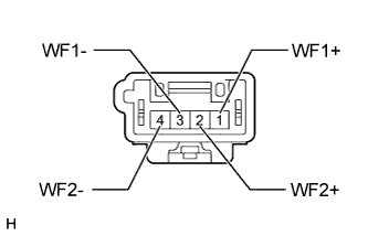
Disconnect the R24 No. 1 speaker with box assembly connector.
-
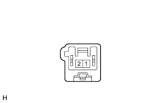
Measure the resistance according to the value(s) in the table below.
Standard Resistance Tester Connection Condition Specified Condition 1 (WF1+) - 3 (WF1-) Always 1.6 to 2.4 Ω 2 (WF2+) - 4 (WF2-) Always 1.6 to 2.4 Ω
NG
REPLACE NO. 1 SPEAKER WITH BOX ASSEMBLY Click here
OK
-
-
CHECK HARNESS AND CONNECTOR (STEREO COMPONENT AMPLIFIER - NO. 1 SPEAKER WITH BOX)
-
Disconnect the H7 stereo component amplifier assembly connector.
-
Disconnect the R24 No. 1 speaker with box assembly connector.
Standard Resistance Tester Connection Condition Specified Condition H7-1 (WF1+) - R24-1 (WF1+) Always Below 1 Ω H7-5 (WF1-) - R24-3 (WF1-) Always Below 1 Ω H7-2 (WF2+) - R24-2 (WF2+) Always Below 1 Ω H7-6 (WF2-) - R24- 4 (WF2-) Always Below 1 Ω H7-1 (WF1+) - Body ground Always 10 kΩ or higher H7-5 (WF1-) - Body ground Always 10 kΩ or higher H7-2 (WF2+) - Body ground Always 10 kΩ or higher H7-6 (WF2-) - Body ground Always 10 kΩ or higher
NG
REPAIR OR REPLACE HARNESS OR CONNECTOR
OK
REPLACE STEREO COMPONENT AMPLIFIER ASSEMBLY Click here
-
-
CHECK SPEAKER
-
Check which speakers are malfunctioning.
Result Result Proceed to Malfunction in front speaker area A Malfunction in rear speaker area B All speakers do not operate C
B
CHECK REAR SIDE SPEAKER Click here
C
REPLACE STEREO COMPONENT AMPLIFIER ASSEMBLY Click here
A
-
-
CHECK FRONT SIDE SPEAKER
-
Check which speakers are malfunctioning.
Result Result Proceed to Front No. 1 speaker assembly A Front No. 3 speaker assembly B Front No. 2 speaker assembly C Front No. 4 speaker assembly D
B
CHECK HARNESS AND CONNECTOR (STEREO COMPONENT AMPLIFIER - FRONT NO. 3 SPEAKER) Click here
C
INSPECT FRONT NO. 2 SPEAKER ASSEMBLY Click here
D
INSPECT FRONT NO. 4 SPEAKER ASSEMBLY Click here
A
-
-
INSPECT FRONT NO. 1 SPEAKER ASSEMBLY
-
Disconnect the H10*1 and/or H13*2 front No. 1 speaker assembly connector.
-
*1: for RH
-
*2: for LH
-
-
Measure the resistance according to the value(s) in the table below.
Standard Resistance Tester Connection Condition Specified Condition 1 - 2 Always 4 Ω
NG
REPLACE FRONT NO. 1 SPEAKER ASSEMBLY Click here
OK
-
-
CHECK HARNESS AND CONNECTOR (FRONT NO. 1 SPEAKER - FRONT NO. 3 SPEAKER)
-
*1: for LH
-
*2: for RH
-
Disconnect the H10*1 and/or H13*2 front No. 1 speaker assembly connector.
-
Disconnect the H21*1 and/or H22*2 front No. 3 speaker assembly connector.
-
Measure the resistance according to the value(s) in the table below.
Standard Resistance for RH Tester Connection Condition Specified Condition H10-1 - H21-4 (-) Always Below 1 Ω H10-2 - H21-3 (+) H10-1 - Body ground Always 10 kΩ or higher H10-2 - Body ground for LH Tester Connection Condition Specified Condition H13-1 - H22-4 (-) Always Below 1 Ω H13-2 - H22-3 (+) H13-1 - Body ground Always 10 kΩ or higher H13-2 - Body ground
NG
REPAIR OR REPLACE HARNESS OR CONNECTOR
OK
-
-
INSPECT FRONT NO. 3 SPEAKER ASSEMBLY
-
Text in Illustration *A for RH *B for LH Disconnect the H21*1 and/or H22*2 front No. 3 speaker assembly connector.
-
*1: for RH
-
*2: for LH
-
-
Measure the resistance according to the value(s) in the table below.
Standard Resistance for RH Tester Connection Condition Specified Condition 1 (TWR+) - 3 (+) Always Below 1 Ω 2 (TWR-) - 4 (-) Always Below 1 Ω for LH Tester Connection Condition Specified Condition 1 (TWL+) - 3 (+) Always Below 1 Ω 2 (TWL-) - 4 (-) Always Below 1 Ω
NG
REPLACE FRONT NO. 3 SPEAKER ASSEMBLY Click here
OK
REPLACE STEREO COMPONENT AMPLIFIER ASSEMBLY Click here
-
-
CHECK HARNESS AND CONNECTOR (STEREO COMPONENT AMPLIFIER - FRONT NO. 3 SPEAKER)
-
Disconnect the H7 stereo component amplifier assembly connector.
-
Disconnect the H21*1 and/or H22*2 front No. 3 speaker assembly connector.
-
*1: for RH
-
*2: for LH
-
-
Measure the resistance according to the value(s) in the table below.
Standard Resistance for RH Tester Connection Condition Specified Condition H7-4 (FR+) - H21-1 (TWR+) Always Below 1 Ω H7-10 (FR-) - H21-2 (TWR-) Always Below 1 Ω H7-4 (FR+) - Body ground Always 10 kΩ or higher H7-10 (FR-) - Body ground Always 10 kΩ or higher for LH Tester Connection Condition Specified Condition H7-3 (FL+) - H22-1 (TWL+) Always Below 1 Ω H7-9 (FL-) - H22-2 (TWL-) Always Below 1 Ω H7-3 (FL+) - Body ground Always 10 kΩ or higher H7-9 (FL-) - Body ground Always 10 kΩ or higher
NG
REPAIR OR REPLACE HARNESS OR CONNECTOR
OK
-
-
INSPECT FRONT NO. 3 SPEAKER ASSEMBLY
-
Temporarily replace the front No. 3 speaker assembly with a new or normally functioning one Click here.
-
Check that the speaker sounds normally.
OK Malfunction disappears.
NG
REPLACE FRONT NO. 3 SPEAKER ASSEMBLY Click here
OK
END
-
-
INSPECT FRONT NO. 2 SPEAKER ASSEMBLY
-
Disconnect the J4*1 and/or K3*2 front No. 2 speaker assembly connector.
-
*1: for RH
-
*2: for LH
-
-
Measure the resistance according to the value(s) in the table below.
Standard Resistance Tester Connection Condition Specified Condition 1 - 2 Always 4 Ω
NG
REPLACE FRONT NO. 2 SPEAKER ASSEMBLY Click here
OK
-
-
CHECK HARNESS AND CONNECTOR (STEREO COMPONENT AMPLIFIER - FRONT NO. 2 SPEAKER)
-
Disconnect the H12 stereo component amplifier assembly connector.
-
Disconnect the J4*1 and/or K3*2 front No. 2 speaker assembly connector.
-
*1: for RH
-
*2: for LH
Measure the resistance according to the value(s) in the table below.
Standard Resistance for RH Tester Connection Condition Specified Condition H12-10 (WFR+) - J4-1 Always Below 1 Ω H12-9 (WFR-) - J4-2 Always Below 1 Ω H12-10 (WFR+) - Body ground Always 10 kΩ or higher H12-9 (WFR-) - Body ground Always 10 kΩ or higher for LH Tester Connection Condition Specified Condition H12-3 (WFL+) - K3-1 Always Below 1 Ω H12-8 (WFL-) - K3-2 Always Below 1 Ω H12-3 (WFL+) - Body ground Always 10 kΩ or higher H12-8 (WFL-) - Body ground Always 10 kΩ or higher -
NG
REPAIR OR REPLACE HARNESS OR CONNECTOR
OK
REPLACE STEREO COMPONENT AMPLIFIER ASSEMBLY Click here
-
-
INSPECT FRONT NO. 4 SPEAKER ASSEMBLY
-
Disconnect the H14 front No. 4 speaker assembly connector.
-
Measure the resistance according to the value(s) in the table below.
Standard Resistance Tester Connection Condition Specified Condition 1 - 2 Always 6 Ω
NG
REPLACE FRONT NO. 4 SPEAKER ASSEMBLY Click here
OK
-
-
CHECK HARNESS AND CONNECTOR (STEREO COMPONENT AMPLIFIER - FRONT NO. 4 SPEAKER)
-
Disconnect the H7 stereo component amplifier assembly connector.
-
Disconnect the H14 front No. 4 speaker assembly connector.
Measure the resistance according to the value(s) in the table below.
Standard Resistance Tester Connection Condition Specified Condition H7-8 (CTR+) - H14-2 Always Below 1 Ω H7-7 (CTR-) - H14-1 Always Below 1 Ω H7-8 (CTR+) - Body ground Always 10 kΩ or higher H7-7 (CTR-) - Body ground Always 10 kΩ or higher
NG
REPAIR OR REPLACE HARNESS OR CONNECTOR
OK
REPLACE STEREO COMPONENT AMPLIFIER ASSEMBLY Click here
-
-
CHECK REAR SIDE SPEAKER
-
Check which speakers are malfunctioning.
Result Result Proceed to Rear speaker set A Rear No. 2 speaker assembly* B Rear header speaker assembly C No. 1 speaker with box assembly D
-
*: for 5 Door
-
B
CHECK HARNESS AND CONNECTOR (STEREO COMPONENT AMPLIFIER - REAR NO. 2 SPEAKER) Click here
C
INSPECT REAR HEADER SPEAKER ASSEMBLY Click here
D
INSPECT NO. 1 SPEAKER WITH BOX ASSEMBLY Click here
A
-
-
INSPECT REAR SPEAKER SET
-
for 5 Door:
-
Disconnect the L1*1 and/or M1*2 rear speaker set connector.
-
*1: for RH
-
*2: for LH
-
-
Measure the resistance according to the value(s) in the table below.
Standard Resistance Tester Connection Condition Specified Condition 1 - 2 Always 4 Ω
-
-
for 3 Door:
-
Disconnect the Q32*1 and/or R37*2 rear speaker set connector.
-
*1: for RH
-
*2: for LH
-
-
Measure the resistance according to the value(s) in the table below.
Standard Resistance Tester Connection Condition Specified Condition 1 - 2 Always 4 Ω Result Result Proceed to OK (for 5 Door) A OK (for 3 Door) B NG C
-
B
CHECK HARNESS AND CONNECTOR (STEREO COMPONENT AMPLIFIER - REAR SPEAKER SET) Click here
C
REPLACE REAR SPEAKER SET Click here
A
-
-
CHECK HARNESS AND CONNECTOR (REAR SPEAKER SET - REAR NO. 2 SPEAKER)
-
*1: for LH
-
*2: for RH
-
Disconnect the L1*1 and/or M1*2 rear speaker set connector.
-
Disconnect the L3*1 and/or M3*2 rear No. 2 speaker assembly connector.
-
Measure the resistance according to the value(s) in the table below.
Standard Resistance for RH Tester Connection Condition Specified Condition L1-1 - L3-3 (+) Always Below 1 Ω L1-2 - L3-4 (-) Always Below 1 Ω L1-1 - Body ground Always 10 kΩ or higher L1-2 - Body ground Always 10 kΩ or higher for LH Tester Connection Condition Specified Condition M1-1 - M3-3 (+) Always Below 1 Ω M1-2 - M3-4 (-) Always Below 1 Ω M1-1 - Body ground Always 10 kΩ or higher M1-2 - Body ground Always 10 kΩ or higher
NG
REPAIR OR REPLACE HARNESS OR CONNECTOR
OK
-
-
INSPECT REAR NO. 2 SPEAKER ASSEMBLY
-
Disconnect the L3*1 and/or M3*2 rear No. 2 speaker assembly connector.
-
*1: for RH
-
*2: for LH
-
-
Measure the resistance according to the value(s) in the table below.
Standard Resistance Tester Connection Condition Specified Condition 1 (+TW) - 3 (+) Always Below 1 Ω 2 (-TW) - 4 (-) Always Below 1 Ω
NG
REPLACE REAR NO. 2 SPEAKER ASSEMBLY Click here
OK
REPLACE STEREO COMPONENT AMPLIFIER ASSEMBLY Click here
-
-
CHECK HARNESS AND CONNECTOR (STEREO COMPONENT AMPLIFIER - REAR SPEAKER SET)
-
Disconnect the H12 stereo component amplifier assembly connector.
-
Disconnect the Q32*1 and/or R37*2 rear speaker set connector.
-
*1: for RH
-
*2: for LH
-
-
Measure the resistance according to the value(s) in the table below.
Standard Resistance for RH Tester Connection Condition Specified Condition H12-5 (RR+) - Q32-1 Always Below 1 Ω H12-12 (RR-) - Q32-2 Always Below 1 Ω H12-5 (RR+) - Body ground Always 10 kΩ or higher H12-12 (RR-) - Body ground Always 10 kΩ or higher for LH Tester Connection Condition Specified Condition H12-4 (RL+) - R37-1 Always Below 1 Ω H12-11 (RL-) - R37-2 Always Below 1 Ω H12-4 (RL+) - Body ground Always 10 kΩ or higher H12-11 (RL-) - Body ground Always 10 kΩ or higher
NG
REPAIR OR REPLACE HARNESS OR CONNECTOR
OK
REPLACE STEREO COMPONENT AMPLIFIER ASSEMBLY Click here
-
-
CHECK HARNESS AND CONNECTOR (STEREO COMPONENT AMPLIFIER - REAR NO. 2 SPEAKER)
-
Disconnect the H12 stereo component amplifier assembly connector.
-
Disconnect the L3*1 and/or M3*2 rear No. 2 speaker assembly connector.
-
*1: for RH
-
*2: for LH
-
-
Measure the resistance according to the value(s) in the table below.
Standard Resistance for RH Tester Connection Condition Specified Condition H12-5 (RR+) - L3-1 (+TW) Always Below 1 Ω H12-12 (RR-) - L3-2 (-TW) Always Below 1 Ω H12-5 (RR+) - Body ground Always 10 kΩ or higher H12-12 (RR-) - Body ground Always 10 kΩ or higher for LH Tester Connection Condition Specified Condition H12-4 (RL+) - M3-1 (+TW) Always Below 1 Ω H12-11 (RL-) - M3-2 (-TW) Always Below 1 Ω H12-4 (RL+) - Body ground Always 10 kΩ or higher H12-11 (RL-) - Body ground Always 10 kΩ or higher
NG
REPAIR OR REPLACE HARNESS OR CONNECTOR
OK
-
-
INSPECT REAR NO. 2 SPEAKER ASSEMBLY
-
Temporarily replace the rear No. 2 speaker assembly with a new or normally functioning one Click here.
-
Check that the speaker sounds normally.
OK Malfunction disappears.
NG
REPLACE STEREO COMPONENT AMPLIFIER ASSEMBLY Click here
OK
END
-
-
INSPECT REAR HEADER SPEAKER ASSEMBLY
-
Disconnect the Q15*1 and/or R13*2 rear header speaker assembly connector.
-
*1: for RH
-
*2: for LH
-
-
Measure the resistance according to the value(s) in the table below.
Standard Resistance Tester Connection Condition Specified Condition 1 - 2 Always 6 Ω
NG
REPLACE REAR HEADER SPEAKER ASSEMBLY Click here
OK
-
-
CHECK HARNESS AND CONNECTOR (STEREO COMPONENT AMPLIFIER - REAR HEADER SPEAKER)
-
Disconnect the H12 stereo component amplifier assembly connector.
-
Disconnect the Q15*1 and/or R13*2 rear header speaker assembly connector.
-
*1: for RH
-
*2: for LH
-
-
Measure the resistance according to the value(s) in the table below.
Standard Resistance for RH Tester Connection Condition Specified Condition H12-2 (MR+) - Q15-2 Always Below 1 Ω H12-7 (MR-) - Q15-1 H12-2 (MR+) - Body ground Always 10 kΩ or higher H12-7 (MR-) - Body ground for LH Tester Connection Condition Specified Condition H12-1 (ML+) - R13-2 Always Below 1 Ω H12-6 (ML-) - R13-1 H12-1 (ML+) - Body ground Always 10 kΩ or higher H12-6 (ML-) - Body ground
NG
REPAIR OR REPLACE HARNESS OR CONNECTOR
OK
REPLACE STEREO COMPONENT AMPLIFIER ASSEMBLY Click here
-
-
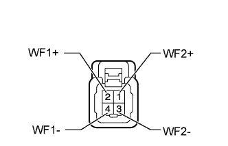
INSPECT NO. 1 SPEAKER WITH BOX ASSEMBLY
-
for 5 Door:
-
Disconnect the R24 No. 1 speaker with box assembly connector.
-
Measure the resistance according to the value(s) in the table below.
Standard Resistance Tester Connection Condition Specified Condition 1 (WF1+) - 3 (WF1-) Always 3 Ω 2 (WF2+) - 4 (WF2-) Always 3 Ω
-
-
for 3 Door:
-
Disconnect the Q30 No. 1 speaker with box assembly connector.
-
Measure the resistance according to the value(s) in the table below.
Standard Resistance Tester Connection Condition Specified Condition 1 (WF2+) - 3 (WF2-) Always 4 Ω 2 (WF1+) - 4 (WF1-) Always 4 Ω Result Result Proceed to OK A NG (for 5 Door) B NG (for 3 Door) C
-
B
REPLACE NO. 1 SPEAKER WITH BOX ASSEMBLY Click here
C
REPLACE NO. 1 SPEAKER WITH BOX ASSEMBLY
A
-
-
CHECK HARNESS AND CONNECTOR (STEREO COMPONENT AMPLIFIER - NO. 1 SPEAKER WITH BOX)
-
Disconnect the H7 stereo component amplifier assembly connector.
-
Disconnect the R24*1 and/or Q30*2 No. 1 speaker with box assembly connector.
-
*1: for 5 Door
-
*2: for 3 Door
Standard Resistance for 5 Door Tester Connection Condition Specified Condition H7-1 (WF1+) - R24-1 (WF1+) Always Below 1 Ω H7-5 (WF1-) - R24-3 (WF1-) Always Below 1 Ω H7-2 (WF2+) - R24-2 (WF2+) Always Below 1 Ω H7-6 (WF2-) - R24-4 (WF2-) Always Below 1 Ω H7-1 (WF1+) - Body ground Always 10 kΩ or higher H7-5 (WF1-) - Body ground Always 10 kΩ or higher H7-2 (WF2+) - Body ground Always 10 kΩ or higher H7-6 (WF2-) - Body ground Always 10 kΩ or higher for 3 Door Tester Connection Condition Specified Condition H7-1 (WF1+) - Q30-2 (WF1+) Always Below 1 Ω H7-5 (WF1-) - Q30-4 (WF1-) Always Below 1 Ω H7-2 (WF2+) - Q30-1 (WF2+) Always Below 1 Ω H7-6 (WF2-) - Q30-3 (WF2-) Always Below 1 Ω H7-1 (WF1+) - Body ground Always 10 kΩ or higher H7-5 (WF1-) - Body ground Always 10 kΩ or higher H7-2 (WF2+) - Body ground Always 10 kΩ or higher H7-6 (WF2-) - Body ground Always 10 kΩ or higher -
NG
REPAIR OR REPLACE HARNESS OR CONNECTOR
OK
REPLACE STEREO COMPONENT AMPLIFIER ASSEMBLY Click here
-