AUDIO AND VISUAL SYSTEM (w/ Navigation System) Illumination Circuit
DESCRIPTION
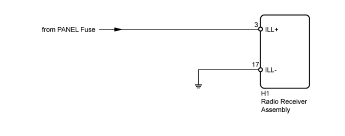
Power is supplied to the radio receiver assembly illumination when the light control switch is in the tail or head position.
WIRING DIAGRAM
INSPECTION PROCEDURE
PROCEDURE
-
CHECK ILLUMINATION
-
Check if the illumination for the radio receiver assembly, heater control switch or others (hazard switch, transmission control switch, etc.) comes on when the light control switch is turned to the head or tail position.
Result Result Proceed to Illumination comes on for all components except radio receiver assembly A No illumination comes on (radio receiver assembly, hazard switch, heater control switch, etc.) B
B 
GO TO LIGHTING SYSTEM Click here
A 
-
-
CHECK HARNESS AND CONNECTOR (BATTERY - RADIO RECEIVER ASSEMBLY)
-
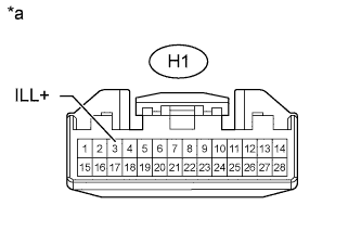
Text in Illustration *a Front view of wire harness connector
(to Radio Receiver Assembly)
Disconnect the H1 radio receiver assembly connector.
-
Measure the voltage according to the value(s) in the table below.
Standard Voltage Tester Connection Switch Condition Specified Condition H1-3 (ILL+) - Body ground Light control switch tail or head 11 to 14 V
NG
REPAIR OR REPLACE HARNESS OR CONNECTOR
OK
-
-
CHECK HARNESS AND CONNECTOR (RADIO RECEIVER - BODY GROUND)
-
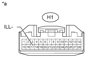
Disconnect the H1 radio receiver assembly connector.
-
Measure the resistance according to the value(s) in the table below.
Standard Resistance Tester Connection Condition Specified Condition H1-17 (ILL-) - Body ground Always 10 kΩ or higher
NG
REPAIR OR REPLACE HARNESS OR CONNECTOR
OK 
PROCEED TO NEXT SUSPECTED AREA SHOWN IN PROBLEM SYMPTOMS TABLE Click here
-