STEERING WHEEL INSPECTION

-
INSPECT STEERING PAD SWITCH ASSEMBLY (w/ Audio + Monitor + Tel + Voice + Multi Function + Distance Control)
-
Inspect the pad switch.
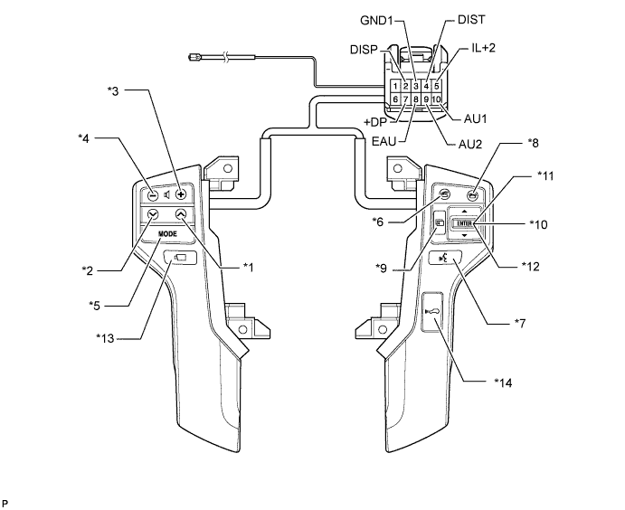
Text in Illustration *1 Seek+ Switch *2 Seek- Switch *3 Volume+ Switch *4 Volume- Switch *5 MODE Switch *6 Off Hook Switch *7 Voice Switch *8 On Hook Switch *9 Menu Switch *10 ENTER Switch *11 UP/DOWN Up Switch *12 UP/DOWN Down Switch *13 Wide View Front and Side Monitor Switch *14 Distance Control Switch
-
Measure the resistance according to the value(s) in the table below.
Standard Resistance Tester Connection Condition Specified Condition 10 (AU1) - 8 (EAU) No switch pushed 95 to 105 kΩ Seek+ switch pushed Below 2.5 Ω Seek- switch pushed 313 to 345 Ω Volume+ switch pushed 950 to 1050 Ω Volume- switch pushed 2950 to 3265 Ω 9 (AU2) - 8 (EAU) No switch pushed 95 to 105 kΩ MODE switch pushed Below 2.5 Ω On hook switch pushed 313 to 345 Ω Off hook switch pushed 950 to 1050 Ω Voice switch pushed 2950 to 3265 Ω 2 (DISP) - 3 (GND1) Menu switch pushed Below 2.5 Ω ENTER switch pushed 313 to 345 Ω UP/DOWN Up switch pushed 2950 to 3265 Ω UP/DOWN Down switch pushed 950 to 1050 Ω 7 (+DP) - 3 (GND1) Wide View Front and Side Monitor switch pushed Below 2.5 Ω 4 (DIST) - 6 (ECC) Distance Control switch pushed Below 2.5 Ω If the result is not as specified, replace the steering pad switch assembly.
-
-
Check the illumination.
-
Connect the battery positive (+) lead to terminals IL+2 and the negative (-) lead to terminals EAU and GND1 of the steering pad switch assembly connector.
-
Check that the switch illumination comes on.
OK Steering pad switch illumination comes on. If the result is not as specified, replace the steering pad switch assembly.
-
-
-
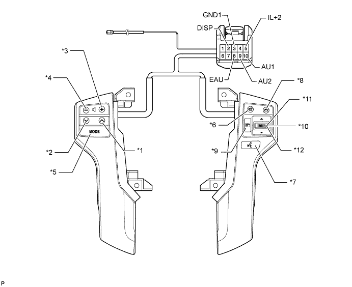
INSPECT STEERING PAD SWITCH ASSEMBLY (w/ Audio + Monitor + Tel + Voice + Multi Function)
-
Inspect the pad switch.

Text in Illustration *1 Seek+ Switch *2 Seek- Switch *3 Volume+ Switch *4 Volume- Switch *5 MODE Switch *6 Off Hook Switch *7 Voice Switch *8 On Hook Switch *9 Menu Switch *10 ENTER Switch *11 UP/DOWN Up Switch *12 UP/DOWN Down Switch *13 Wide View Front and Side Monitor Switch - -
-
Measure the resistance according to the value(s) in the table below.
Standard Resistance Tester Connection Condition Specified Condition 10 (AU1) - 8 (EAU) No switch pushed 95 to 105 kΩ Seek+ switch pushed Below 2.5 Ω Seek- switch pushed 313 to 345 Ω Volume+ switch pushed 950 to 1050 Ω Volume- switch pushed 2950 to 3265 Ω 9 (AU2) - 8 (EAU) No switch pushed 95 to 105 kΩ MODE switch pushed Below 2.5 Ω On hook switch pushed 313 to 345 Ω Off hook switch pushed 950 to 1050 Ω Voice switch pushed 2950 to 3265 Ω 2 (DISP) - 3 (GND1) Menu switch pushed Below 2.5 Ω ENTER switch pushed 313 to 345 Ω UP/DOWN Up switch pushed 2950 to 3265 Ω UP/DOWN Down switch pushed 950 to 1050 Ω 7 (+DP) - 3 (GND1) Wide View Front and Side Monitor switch pushed Below 2.5 Ω If the result is not as specified, replace the steering pad switch assembly.
-
-
Check the illumination.
-
Connect the battery positive (+) lead to terminals IL+2 and the negative (-) lead to terminals EAU and GND1 of the steering pad switch assembly connector.
-
Check that the switch illumination comes on.
OK Steering pad switch illumination comes on. If the result is not as specified, replace the steering pad switch assembly.
-
-
-
INSPECT STEERING PAD SWITCH ASSEMBLY (w/ Audio + Tel + Voice + Multi Function)
-
Inspect the pad switch.
Text in Illustration *1 Seek+ Switch *2 Seek- Switch *3 Volume+ Switch *4 Volume- Switch *5 MODE Switch *6 Off Hook Switch *7 Voice Switch *8 On Hook Switch *9 Menu Switch *10 ENTER Switch *11 UP/DOWN Up Switch *12 UP/DOWN Down Switch
-
Measure the resistance according to the value(s) in the table below.
Standard Resistance Tester Connection Condition Specified Condition 10 (AU1) - 8 (EAU) No switch pushed 95 to 105 kΩ Seek+ switch pushed Below 2.5 Ω Seek- switch pushed 313 to 345 Ω Volume+ switch pushed 950 to 1050 Ω Volume- switch pushed 2950 to 3265 Ω 9 (AU2) - 8 (EAU) No switch pushed 95 to 105 kΩ MODE switch pushed Below 2.5 Ω On hook switch pushed 313 to 345 Ω Off hook switch pushed 950 to 1050 Ω Voice switch pushed 2950 to 3265 Ω 2 (DISP) - 3 (GND1) Menu switch pushed Below 2.5 Ω ENTER switch pushed 313 to 345 Ω UP/DOWN Up switch pushed 2950 to 3265 Ω UP/DOWN Down switch pushed 950 to 1050 Ω If the result is not as specified, replace the steering pad switch assembly.
-
-
Check the illumination.
-
Connect the battery positive (+) lead to terminals IL+2 and the negative (-) lead to terminals EAU and GND1 of the steering pad switch assembly connector.
-
Check that the switch illumination comes on.
OK Steering pad switch illumination comes on. If the result is not as specified, replace the steering pad switch assembly.
-
-
-
INSPECT STEERING PAD SWITCH ASSEMBLY (w/ Audio + Tel + Voice)
-
Inspect the pad switch.
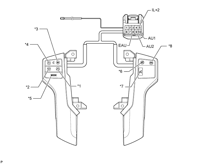
Text in Illustration *1 Seek+ Switch *2 Seek- Switch *3 Volume+ Switch *4 Volume- Switch *5 MODE Switch *6 Off Hook Switch *7 Voice Switch *8 On Hook Switch
-
Measure the resistance according to the value(s) in the table below.
Standard Resistance Tester Connection Condition Specified Condition 10 (AU1) - 8 (EAU) No switch pushed 95 to 105 kΩ Seek+ switch pushed Below 2.5 Ω Seek- switch pushed 313 to 345 Ω Volume+ switch pushed 950 to 1050 Ω Volume- switch pushed 2950 to 3265 Ω 9 (AU2) - 8 (EAU) No switch pushed 95 to 105 kΩ MODE switch pushed Below 2.5 Ω On hook switch pushed 313 to 345 Ω Off hook switch pushed 950 to 1050 Ω Voice switch pushed 2950 to 3265 Ω If the result is not as specified, replace the steering pad switch assembly.
-
-
Check the illumination.
-
Connect the battery positive (+) lead to terminals IL+2 and the negative (-) lead to terminals EAU of the steering pad switch assembly connector.
-
Check that the switch illumination comes on.
OK Steering pad switch illumination comes on. If the result is not as specified, replace the steering pad switch assembly.
-
-
-
INSPECT STEERING PAD SWITCH RH (w/ Multi Function)
-
Inspect the pad switch.
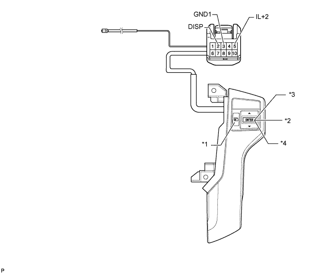
Text in Illustration *1 Menu Switch *2 ENTER Switch *3 UP/DOWN Up Switch *4 UP/DOWN Down Switch
-
Measure the resistance according to the value(s) in the table below.
Standard Resistance Tester Connection Condition Specified Condition 2 (DISP) - 3 (GND1) No switch pushed 95 to 105 kΩ Menu switch pushed Below 2.5 Ω ENTER switch pushed 313 to 345 Ω UP/DOWN Up switch pushed 2950 to 3265 Ω UP/DOWN Down switch pushed 950 to 1050 Ω If the result is not as specified, replace the steering pad switch RH.
-
-
Check the illumination.
-
Connect the battery positive (+) lead to terminals IL+2 and the negative (-) lead to terminals GND1 of the steering pad RH connector.
-
Check that the switch illumination comes on.
OK Steering pad switch illumination comes on. If the result is not as specified, replace the steering pad switch assembly.
-
-