POWER STEERING ECU INSTALLATION

Tech Tips
A bolt without a torque specification is shown in the standard bolt chart Click here.
-
INSTALL POWER STEERING ECU ASSEMBLY
-
Attach the 2 claws to install the power steering ECU assembly.
-
-
INSTALL ECU INTEGRATION BOX RH
-
Install the ECU integration box RH with the 2 nuts and bolt.
-
Attach the clamp.
-
Connect the connectors.
-
-
INSTALL NO. 2 AIR DUCT SUB-ASSEMBLY
-
Attach the 2 claws to install the No. 2 air duct sub-assembly.
-
Install the screw.
-
-
INSTALL GLOVE COMPARTMENT DOOR ASSEMBLY
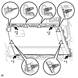
Text in Illustration *1 Bolt *2 Screw
-
Connect each connector.
-
Attach the 5 clips and claw to install the glove compartment door.
-
Install the 2 bolts <C> and 2 screws <A> or <B>.
-
-
INSTALL INSTRUMENT PANEL ORNAMENT
-
for LHD:
-
Attach the 2 guides to install the instrument panel safety pad.
-
Install the 2 brackets with the 4 bolts and 2 nuts.
-
Connect the connectors and attach the clamps and claws.
-
Install the 2 passenger airbag bolts <G>.
- Torque:
- 20 N*m { 204 kgf*cm, 15 ft.*lbf }
-
Install the 6 bolts <E> and nut <F>.
-
Install the front floor carpet.
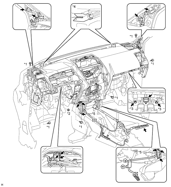
Text in Illustration *1 Bolt <E> *2 Nut <F> *3 Bolt <G> *4 Guide *5 Bracket - -
-
-
for RHD:
-
Attach the 2 guides to install the instrument panel safety pad.
-
Install the 2 brackets with the 4 bolts and 2 nuts.
-
Connect the connectors and attach the clamps and claws.
-
Install the 2 passenger airbag bolts <G>.
- Torque:
- 20 N*m { 204 kgf*cm, 15 ft.*lbf }
-
Install the 6 bolts <E> and nut <F>.
-
Install the front floor carpet.
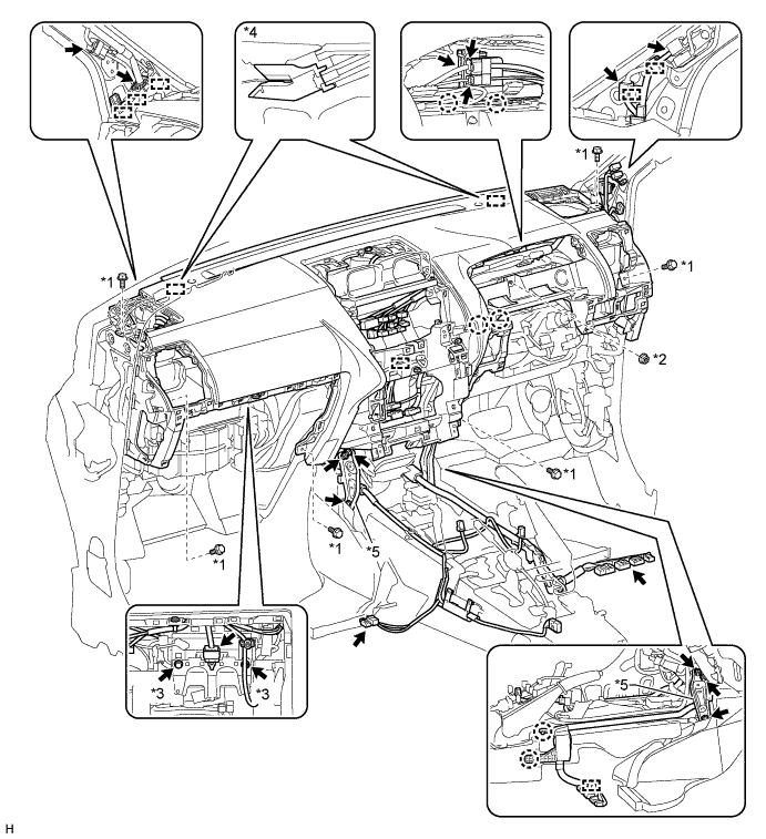
Text in Illustration *1 Bolt <E> *2 Nut <F> *3 Bolt <G> *4 Guide *5 Bracket - -
-
-
-
INSTALL INSTRUMENT SIDE PANEL RH
-
Connect the connector.
-
Attach the 5 clips, claw and 3 guides to install the instrument side panel.
-
-
INSTALL NO. 2 INSTRUMENT PANEL UNDER COVER SUB-ASSEMBLY
-
Attach the 3 clips and 2 guides to install the No. 2 instrument panel under cover.
-
Install the screw.
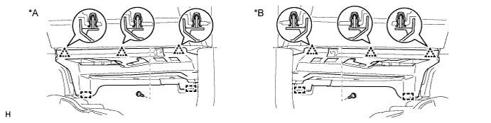
Text in Illustration *A for LHD *B for RHD
-
-
INSTALL COWL SIDE TRIM BOARD RH
-
Attach the clip and claw to install the cowl side trim board.
-
Install the clip.
-
-
INSTALL DOOR SCUFF PLATE ASSEMBLY RH
-
Attach the 4 clips, 10 claws and 2 guides to install the door scuff plate.
-
-
CONNECT CABLE TO NEGATIVE BATTERY TERMINAL
Note
When disconnecting the cable, some systems need to be initialized after the cable is reconnected Click here.
-
CHECK SRS WARNING LIGHT