VANE PUMP (for 1GR-FE) INSTALLATION

-
INSTALL VANE PUMP ASSEMBLY
-
Install the vane pump with the 2 bolts.
- Torque:
- 43 N*m { 438 kgf*cm, 32 ft.*lbf }
-
Install the wire harness bracket with the bolt.
- Torque:
- 43 N*m { 438 kgf*cm, 32 ft.*lbf }
-
-
CONNECT PRESSURE FEED TUBE
-
Install a new gasket to the pressure feed tube.
-
Connect the pressure feed tube and install the union bolt.
- Torque:
- 50 N*m { 510 kgf*cm, 37 ft.*lbf }
Tech Tips
Make sure the stopper of the pressure feed tube touches the vane pump.
-
-
CONNECT NO. 1 OIL RESERVOIR TO PUMP HOSE
-
Connect the No. 1 oil reservoir to pump hose to the vane pump assembly with the clip.
-
-
CONNECT POWER STEERING OIL PRESSURE SWITCH CONNECTOR
-
Connect the 2 connectors.
-
-
INSTALL FAN AND GENERATOR V BELT
-
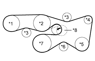
Text in Illustration *1 Vane Pump *2 Water Pump *3 No. 2 Idler *4 Generator *5 Cooler Compressor or Idler Pulley *6 No. 1 Idler *7 Crankshaft *8 V-ribbed Belt Tensioner Set the V belt onto every part.
-
While turning the belt tensioner counterclockwise, remove the pin.
Note
Make sure that the V belt is properly installed to each pulley.
-
Check that the belt fits properly in the ribbed grooves.
Tech Tips
Make sure to check by hand that the belt has not slipped out of the grooves on the bottom of the pulley.
-
-
INSTALL AIR CLEANER CASE
-
INSTALL AIR CLEANER FILTER ELEMENT SUB-ASSEMBLY
-
INSTALL AIR CLEANER CAP AND HOSE
-
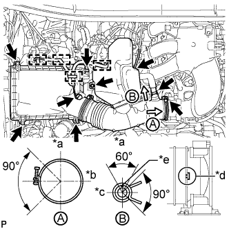
Text in Illustration *a Top *b Front *c RH *d Align cutout portion of hose with protrusion of throttle *e Paint Mark Install the air cleaner cap and hose.
-
Install the air cleaner cap and hose with the bolt and fasten the 4 hook clamps.
- Torque:
- 5.0 N*m { 51 kgf*cm, 44 in.*lbf }
-
Tighten the clamp.
- Torque:
- 5.0 N*m { 51 kgf*cm, 44 in.*lbf }
-
Attach the 4 clamps and connect the ventilation hose, vacuum hose and mass air flow meter connector.
Tech Tips
The direction of the hose clamp is indicated in the illustration.
-
-
-
INSTALL V-BANK COVER SUB-ASSEMBLY
-

Text in Illustration *1 Pin *2 Hook Attach the 2 V-bank cover hooks to the bracket. Then align the 2 V-bank cover grommets with the 2 pins and press down on the V-bank cover to attach the pins.
-
-
INSTALL FRONT FENDER APRON SEAL RH
-
Install the apron seal with the 5 clips.
-
-
INSTALL FRONT WHEEL RH
- Torque:
- 112 N*m { 1137 kgf*cm, 82 ft.*lbf }
-
CONNECT CABLE TO NEGATIVE BATTERY TERMINAL
-
ADD POWER STEERING FLUID
-
BLEED POWER STEERING FLUID
-
Check the fluid level.
-
Jack up the front of the vehicle and support it with stands.
-
Turn the steering wheel.
-
With the engine stopped, turn the wheel slowly from lock to lock several times.
-
-
Lower the vehicle.
-
Start the engine.
-
Run the engine at idle for a few minutes.
-
-
Turn the steering wheel.
-
With the engine idling, turn the wheel to the left or right full lock position and keep it there for 2 to 3 seconds, then turn the wheel to the opposite full lock position and keep it there for 2 to 3 seconds.*1
-
Repeat *1 several times.
-
-
Stop the engine.
-
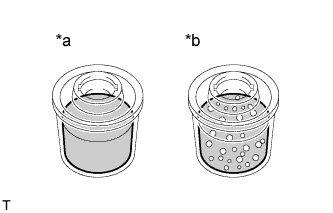
Text in Illustration *a CORRECT *b INCORRECT Check for foaming or emulsification.
If the system has to be bled twice specifically because of foaming or emulsification, check for fluid leaks in the power steering system.
-
Check the fluid level.
-
-
INSPECT FOR POWER STEERING FLUID LEAK