PARKING BRAKE CABLE INSTALLATION

-
INSTALL NO. 3 PARKING BRAKE CABLE ASSEMBLY
-
for 3 Door:
-
Install the No. 4 parking brake cable clamp with the bolt.
- Torque:
- 13 N*m { 127 kgf*cm, 9 ft.*lbf }
-
Attach the No. 2 parking brake cable clamp to the No. 3 parking brake cable.
-
Install the No. 3 parking brake cable with the 2 bolts and 3 nuts.
- Torque:
- 13 N*m { 127 kgf*cm, 9 ft.*lbf }
-
-
for 5 Door:
-
Attach the No. 3 parking brake cable clamp to the No. 3 parking brake cable.
-
Install the No. 3 parking brake cable with the 4 bolts.
- Torque:
- 13 N*m { 127 kgf*cm, 9 ft.*lbf }
-
Install the No. 1 parking brake cable heat insulator.
- Torque:
- 13 N*m { 127 kgf*cm, 9 ft.*lbf }
-
-
Attach the claws of the No. 3 parking brake cable.
-
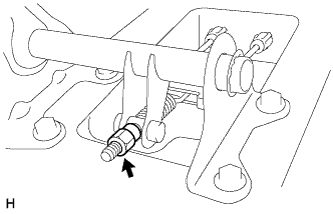
Connect the No. 3 parking brake cable to the No. 1 parking brake pull rod.
-
Install the No. 3 parking brake cable assembly to the backing plate with the 2 bolts.
- Torque:
- 8.0 N*m { 82 kgf*cm, 71 in.*lbf }
-
-
INSTALL NO. 2 PARKING BRAKE CABLE ASSEMBLY
-
for 3 Door:
-
Install the No. 3 parking brake cable clamp with the bolt.
- Torque:
- 13 N*m { 127 kgf*cm, 9 ft.*lbf }
-
Attach the No. 1 parking brake cable clamp to the No. 2 parking brake cable.
-
Install the No. 2 parking brake cable with the 2 bolts and 3 nuts.
- Torque:
- 13 N*m { 127 kgf*cm, 9 ft.*lbf }
-
-
for 5 Door:
-
Attach the No. 2 parking brake cable clamp to the No. 2 parking brake cable.
-
Install the No. 2 parking brake cable with the 5 bolts.
- Torque:
- 13 N*m { 127 kgf*cm, 9 ft.*lbf }
-
-
Attach the claws of the No. 2 parking brake cable.
-
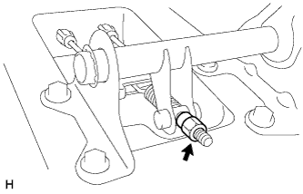
Connect the No. 2 parking brake cable to the No. 1 parking brake pull rod.
-
Install the No. 2 parking brake cable assembly to the backing plate with the 2 bolts.
- Torque:
- 8.0 N*m { 82 kgf*cm, 71 in.*lbf }
-
-
CONNECT NO. 2 PARKING BRAKE SHOE ASSEMBLY WITH PARKING BRAKE SHOE LEVER
Tech Tips
Refer to the procedures from "Install No. 2 Parking Brake Shoe Assembly with Parking Brake Shoe Lever" Click here.
-
INSTALL FUEL TANK SUB-ASSEMBLY
-
for 1GR-FE:
Install the fuel tank sub-assembly Click here.
-
for 1KD-FTV, for 3 Door:
Install the fuel tank sub-assembly Click here.
-
for 1KD-FTV, for 5 Door:
Install the fuel tank sub-assembly Click here.
-
for 2TR-FE, for 3 Door:
Install the fuel tank sub-assembly Click here.
-
for 2TR-FE, for 5 Door:
Install the fuel tank sub-assembly Click here.
-
for 5L-E:
Install the fuel tank sub-assembly Click here.
-
-
INSTALL CENTER EXHAUST PIPE ASSEMBLY (for 3 Door)
-
for 1KD-FTV:
Install the center exhaust pipe assembly Click here.
-
for 2TR-FE:
Install the center exhaust pipe assembly Click here.
-
-
INSPECT PARKING BRAKE LEVER TRAVEL
-
Fully pull the parking brake lever to engage the parking brake.
-
Release the lever to disengage the parking brake.
-
Slowly pull the parking brake lever all the way and count the number of clicks.
Standard parking brake lever travel when pulled with a force of 200 N (20 kgf, 45 lbf) 5 to 7 clicks If the parking brake lever travel is not as specified, adjust the parking brake shoe clearance and parking brake lever travel.
-
-
ADJUST PARKING BRAKE LEVER TRAVEL
-
for Automatic Transmission:
Remove the rear console box assembly Click here.
-
for Manual Transmission:
Remove the rear console box assembly Click here.
-
w/ Refrigerated Cool Box:
Remove the rear console box assembly Click here.
-
Completely release the parking brake lever.
-
Loosen the adjusting nut to completely release the parking brake cable.
-
Temporarily install the hub nuts.
-
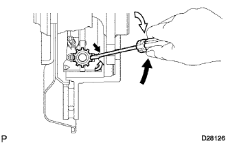
Turn the shoe adjuster so that it expands until the disc locks.
Text in Illustration 
Shoe Adjuster Contracts 
Shoe Adjuster Expands -
Turn the shoe adjuster so that it contracts until the disc can rotate smoothly.
OK 8 notches -
Check that there is no brake drag against the shoe.
-
Install the hole plug.
-
Remove the hub nuts.
-
Turn the adjusting nut until the parking brake lever travel becomes correct.
Standard parking brake lever travel when pulled with a force of 200 N (20 kgf, 45 lbf) 5 to 7 clicks -
Operate the parking brake lever 3 to 4 times and check the parking brake lever travel.
Standard parking brake lever travel when pulled with a force of 200 N (20 kgf, 45 lbf) 5 to 7 clicks -
Check whether the parking brake drags or not.
-
When operating the parking brake lever, check that the brake warning light comes on.
Standard The brake warning light always illuminates at the first click. -
for Automatic Transmission:
Install the rear console box assembly Click here.
-
for Manual Transmission:
Install the rear console box assembly Click here.
-
w/ Refrigerated Cool Box:
Install the rear console box assembly Click here.
-
-
INSTALL REAR CONSOLE BOX ASSEMBLY
-
for Automatic Transmission:
Install the rear console box assembly Click here.
-
for Manual Transmission:
Install the rear console box assembly Click here.
-
w/ Refrigerated Cool Box:
Install the rear console box assembly Click here.
-
-
INSTALL REAR WHEEL
- Torque:
- 112 N*m { 1142 kgf*cm, 83 ft.*lbf }