BRAKE PEDAL (for Hydraulic Brake Booster) ADJUSTMENT

-
CHECK BRAKE PEDAL HEIGHT
-
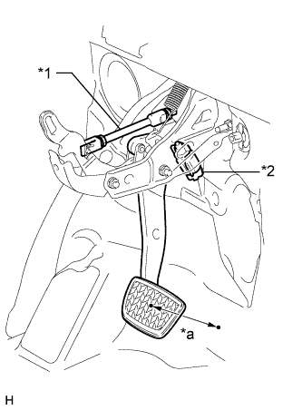
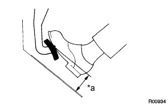
Text in Illustration *a Pedal Height *1 Rod Operating Adapter *2 Stop Light Switch Assembly Check the brake pedal height.
Standard Pedal Height from Dash panel Item Specified Condition for LHD 160.2 to 170.2 mm (6.31 to 6.71 in.) for RHD 160.4 to 170.4 mm (6.31 to 6.71 in.) Tech Tips
The illustration is for LHD vehicles. Check the pedal height for RHD vehicles at the same location as that used for LHD vehicles.
Note
Do not adjust the pedal height. Doing so by changing the push rod length will structurally change the pedal ratio.
If the pedal height is incorrect, adjust the rod operating adapter length.
-
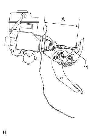
Text in Illustration *1 Clevis Lock Nut Adjust the rod operating adapter length.
-
Remove the clip and clevis pin.
-
Loosen the push rod clevis lock nut.
-
Adjust the rod operating adapter length by turning the pedal push rod clevis.
Standard Rod Operating Adapter Length "A" 236.3 to 237.3 mm (9.30 to 9.34 in.) -
Tighten the push rod clevis lock nut.
- Torque:
- 26 N*m { 260 kgf*cm, 19 ft.*lbf }
-
Install the clip and clevis pin.
If the pedal height is incorrect even if the rod operating adapter is adjusted, check that there is no damage to the brake pedal, brake pedal lever, brake pedal bracket or dash panel.
-
Even if there is damage, there is no problem if the reserve distance is within the standard value.
-
If necessary, replace the clip.
-
-
-
-
CHECK AND ADJUST STOP LIGHT SWITCH ASSEMBLY
Tech Tips
If the pedal height is incorrect, check and adjust the stop light switch clearance.
-
Disconnect the stop light switch assembly connector from the stop light switch assembly.
-
Turn the stop light switch assembly counterclockwise and remove the stop light switch assembly.
-
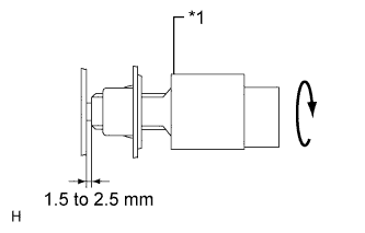
Text in Illustration *1 Stop Light Switch Insert the stop light switch assembly until the body hits the cushion.
Note
When inserting the stop light switch assembly, support the pedal from behind so that the pedal is not pushed in.
-
Make a quarter turn clockwise to install the stop light switch assembly.
Tech Tips
Due to the inverse screw structure, if the stop light switch assembly is turned clockwise, the stop light switch assembly moves in the direction to be pulled out.
Note
The turning torque for installing the stop light switch should be 1.5 N*m (15 kgf*cm, 13 in.*lbf) or less.
-
Connect the stop light switch connector to the stop light switch assembly.
-
Check the protrusion of the rod.
Standard Rod Protrusion 1.5 to 2.5 mm (0.0591 to 0.0984 in.) -
Install the clevis pin and clip.
-
After adjusting the pedal height, check the pedal free play.
-
-
CHECK BRAKE PEDAL FREE PLAY
-
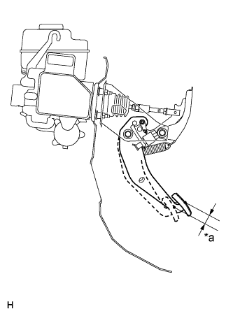
Text in Illustration *a Pedal Free Play Stop the engine and depress the brake pedal several times until there is no more vacuum left in the booster.
-
Push in the pedal until the resistance is felt. Measure the distance.
Standard Pedal Free Play 1 to 6 mm (0.0394 to 0.236 in.) Tech Tips
Check the brake pedal free play at the same location as that used when checking the brake pedal height.
-
-
CHECK BRAKE PEDAL RESERVE DISTANCE
Tech Tips
Measure the distance from the same point used for the brake pedal height inspection.
-
Text in Illustration *a Pedal Reserve Distance Release the parking brake .
-
With the engine running, depress the brake pedal and measure the pedal reserve distance.
Standard Pedal Reserve Distance from asphalt sheet at 490 N (50 kgf, 110.2 lbf) Item Specified Condition for LHD (Manual Transmission) More than 94 mm (3.70 in.) for LHD (Automatic Transmission) More than 101 mm (3.98 in.) for RHD More than 101 mm (3.98 in.) If incorrect, troubleshoot the brake system.
Tech Tips
Insert a ruler into the slit to measure the pedal reserve distance.
-