VEHICLE STABILITY CONTROL SYSTEM (for Vacuum Brake Booster), Diagnostic DTC:C1422

| DTC Code | DTC Name |
|---|---|
| C1422 | Master Cylinder Pressure Sensor Zero Point High Malfunction |
DESCRIPTION
Refer to DTCs C1421, C1423 and C1424 Click here.
| DTC Code | DTC Detection Condition | Trouble Area |
|---|---|---|
| C1422 | When the stop light switch is off, the PMC terminal voltage is higher than 0.86 V for 5 seconds or more. |
|
WIRING DIAGRAM
Refer to DTC C1425 Click here.
INSPECTION PROCEDURE
Note
-
When replacing the brake actuator assembly, perform calibration Click here.
-
Inspect the fuses for circuits related to this system before performing the following inspection procedure.
Tech Tips
When DTC C1425 is output together with DTC C1422, inspect and repair the trouble areas indicated by DTC C1425 first Click here.
PROCEDURE
-
READ VALUE USING INTELLIGENT TESTER (STOP LIGHT SW)
-
Turn the ignition switch off
-
Connect the intelligent tester to the DLC3.
-
Turn the ignition switch to ON.
-
Turn the intelligent tester on.
-
Enter the following menus: Chassis / ABS/VSC/TRC / Data List.
ABS/VSC/TRC Tester Display Measurement Item/Range Normal Condition Diagnostic Note Stop Light SW Stop light switch/ON or OFF ON: Brake pedal depressed
OFF: Brake pedal released
- -
Check that the stop light switch display observed on the intelligent tester changes according to the brake pedal operation.
OK The intelligent tester displays ON or OFF according to brake pedal operation.
NG 
CHECK TERMINAL VOLTAGE (STOP LIGHT SWITCH POWER SOURCE TERMINAL) Click here
OK 
-
-
CHECK BRAKE PEDAL AND STOP LIGHT SWITCH INSTALLATION
-
Turn the ignition switch off.
-
Check the brake pedal height and stop light switch installation Click here.
OK The brake pedal height and stop light switch installation are normal.
NG 
ADJUST BRAKE PEDAL OR STOP LIGHT SWITCH Click here
OK
-
-
RECONFIRM DTC
-
Clear the DTCs Click here.
-
Start the engine.
-
Drive the vehicle at a speed of 40 km/h (25 mph) or more and perform a braking test (decelerate the vehicle by depressing the brake pedal).
-
Check if the same DTC is output Click here.
Result Result Proceed to DTC C1422 is not output A DTC C1422 is output B
B
REPLACE BRAKE ACTUATOR ASSEMBLY Click here
A 
USE SIMULATION METHOD TO CHECK Click here
-
-
CHECK TERMINAL VOLTAGE (STOP LIGHT SWITCH POWER SOURCE TERMINAL)
-
Make sure that there is no looseness at the locking parts and connecting parts of the connectors.
-
Disconnect the A5 stop light switch connector.
-
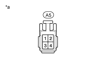
Text in Illustration *a Front view of wire harness connector
(to Stop Light Switch)
Measure the voltage according to the value(s) in the table below.
Standard Voltage Tester Connection Condition Specified Condition A5-2 - Body ground Always 11 to 14 V
NG
REPAIR OR REPLACE HARNESS OR CONNECTOR
OK
-
-
INSPECT STOP LIGHT SWITCH
-
Remove the stop light switch Click here.
-
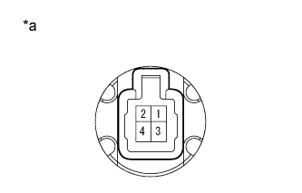
Text in Illustration *a Component without harness connected
(Stop Light Switch)
Measure the resistance according to the value(s) in the table below.
Standard Resistance Tester Connection Switch Condition Specified Condition 1 - 2 Switch pin not pushed in Below 1 Ω Switch pin pushed in 10 kΩ or higher
NG
REPLACE STOP LIGHT SWITCH
OK
-
-
CHECK TERMINAL VOLTAGE (STP)
-
Make sure that there is no looseness at the locking parts and connecting parts of the connectors.
-
Disconnect the A6 skid control ECU connector.
-
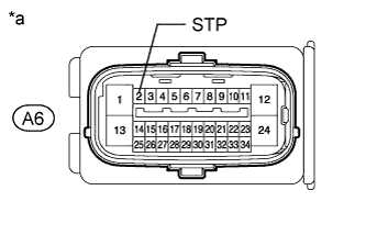
Text in Illustration *a Front view of wire harness connector
(to Skid Control ECU)
Measure the voltage according to the value(s) in the table below.
Standard Voltage Tester Connection Condition Specified Condition A6-2 (STP) - Body ground Brake pedal depressed 8 to 14 V Brake pedal released Below 1.5 V
NG
REPAIR OR REPLACE HARNESS OR CONNECTOR
OK
REPLACE BRAKE ACTUATOR ASSEMBLY Click here
-