VEHICLE STABILITY CONTROL SYSTEM (for Hydraulic Brake Booster) VSC Buzzer Circuit
DESCRIPTION
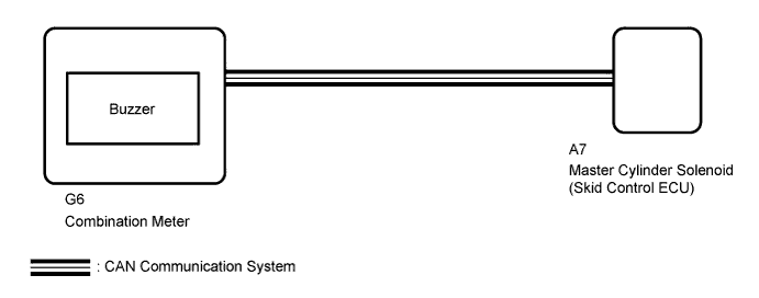
The skid control ECU is connected to the combination meter via CAN communication.
The combination meter has a built-in buzzer. The buzzer sounds during VSC operation.
WIRING DIAGRAM
INSPECTION PROCEDURE
Note
When replacing the master cylinder solenoid, perform calibration Click here.
PROCEDURE
-
CHECK CAN COMMUNICATION LINE
-
Turn the ignition switch off.
-
Connect the intelligent tester to the DLC3.
-
Turn the ignition switch to ON.
-
Turn the intelligent tester on.
-
Select CAN Bus Check from the System Selection Menu screen and follow the prompts on the screen to inspect the CAN bus (for LHD: Click here, for RHD: Click here.
OK CAN Bus Check indicates no malfunctions in CAN communication. Result Result Proceed to OK A NG (for LHD) B NG (for RHD) C
B 
GO TO CAN COMMUNICATION SYSTEM (HOW TO PROCEED WITH TROUBLESHOOTING) Click here
C
GO TO CAN COMMUNICATION SYSTEM (HOW TO PROCEED WITH TROUBLESHOOTING) Click here
A 
-
-
READ VALUE USING INTELLIGENT TESTER (BUZZER)
-
Turn the ignition switch off.
-
Connect the intelligent tester to the DLC3.
-
Turn the ignition switch to ON.
-
Turn the intelligent tester on.
-
Enter the following menus: Chassis / ABS/VSC/TRC / Data List.
ABS/VSC/TRC Tester Display Measurement Item/Range Normal Condition Diagnostic Note Buzzer Buzzer/ ON or OFF ON: Buzzer on
OFF: Buzzer off
The combination meter has a built-in buzzer. -
When performing the Buzzer Active Test, check Buzzer in the Data List Click here.
ABS/VSC/TRC Tester Display Test Part Control Range Diagnostic Note Buzzer Buzzer Buzzer ON/OFF The buzzer can be heard. Result Result Proceed to Data List Display Data List Display when Performing Active Test ON/OFF Operation ON Changes between ON and OFF A Does not change between ON and OFF B OFF Changes between ON and OFF A Does not change between ON and OFF B
B 
INSPECT COMBINATION METER ASSEMBLY Click here
A 
GO TO METER / GAUGE SYSTEM (HOW TO PROCEED WITH TROUBLESHOOTING) Click here
-
-
INSPECT COMBINATION METER ASSEMBLY
-
Inspect the combination meter Click here.
Result Result Proceed to NG A OK (for LHD) B OK (for RHD) C
B
REPLACE MASTER CYLINDER SOLENOID Click here
C
REPLACE MASTER CYLINDER SOLENOID Click here
A
REPLACE COMBINATION METER ASSEMBLY Click here
-