VEHICLE STABILITY CONTROL SYSTEM (for Hydraulic Brake Booster) Crawl Indicator Light does not Come ON
DESCRIPTION
If any of the following conditions are met, the crawl indicator light blinks and crawl control is stopped.
-
Crawl control is operated when the vehicle stability control system is malfunctioning, or a vehicle stability control system malfunction occurs during crawl control.
-
The transfer is shifted to H4 during crawl control.
-
The shift lever is moved to P or N during crawl control.
-
The driver side door is opened during crawl control.
When the vehicle is driven at 25 km/h (16 mph) or more during crawl control, control is temporarily stopped and the crawl indicator light blinks.
When using crawl control continually for a long period of time, if the temperature inside the hydraulic brake booster becomes too high, the crawl indicator light will turn off after blinking. After a while, the temperature decreases and crawl control becomes operable.
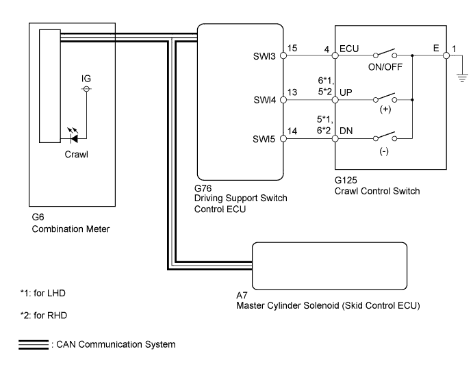
WIRING DIAGRAM
INSPECTION PROCEDURE
Note
When replacing the master cylinder solenoid, perform calibration Click here.
PROCEDURE
-
CHECK CAN COMMUNICATION LINE
-
Turn the ignition switch off.
-
Connect the intelligent tester to the DLC3.
-
Turn the ignition switch to ON.
-
Turn the intelligent tester on.
-
Select CAN Bus Check from the System Selection Menu screen and follow the prompts on the screen to inspect the CAN bus (for LHD: Click here, for RHD: Click here.
OK CAN Bus Check indicates no malfunctions in CAN communication. Result Result Proceed to OK A NG (for LHD) B NG (for RHD) C
B 
GO TO CAN COMMUNICATION SYSTEM (HOW TO PROCEED WITH TROUBLESHOOTING) Click here
C
GO TO CAN COMMUNICATION SYSTEM (HOW TO PROCEED WITH TROUBLESHOOTING) Click here
A 
-
-
CHECK FOR DTC
-
Check for DTCs Click here.
Result Result Proceed to DTC is not output A DTC is output B
B
REPAIR CIRCUITS INDICATED BY OUTPUT DTCS Click here
A
-
-
READ VALUE USING INTELLIGENT TESTER (CRAWL CONTROL SWITCH)
-
Turn the ignition switch off.
-
Connect the intelligent tester to the DLC3.
-
Turn the ignition switch to ON.
-
Turn the intelligent tester on.
-
Enter the following menus: Body Electrical / D-SEAT SW / Data List.
D-SEAT SW Tester Display Measurement Item/Range Normal Condition Diagnostic Note Crawl Control Main Switch Crawl control switch (ON/OFF switch)/ ON or OFF ON: Crawl switch on
OFF: Crawl switch off
- Crawl Control Up Switch Crawl Control Switch (Speed selector switch up side)/ ON or OFF ON: Speed selector switch up side pushed and held
OFF: Speed selector switch up side not pushed
- Crawl Control Down Switch Crawl Control Switch (Speed selector switch down side)/ ON or OFF ON: Speed selector switch down side pushed and held
OFF: Speed selector switch down side not pushed
- OK The intelligent tester displays ON or OFF according to crawl control switch operation.
NG 
OK
-
-
READ VALUE USING INTELLIGENT TESTER (CRAWL CONTROL LIGHT)
-
Turn the ignition switch off.
-
Connect the intelligent tester to the DLC3.
-
Turn the ignition switch to ON.
-
Turn the intelligent tester on.
-
Enter the following menus: Chassis / ABS/VSC/TRC / Data List.
ABS/VSC/TRC Tester Display Measurement Item/Range Normal Condition Diagnostic Note Crawl Control Light Crawl indicator light/ ON or OFF ON: Indicator light on
OFF: Indicator light off
- -
When performing the Crawl Control Light Active Test, check Crawl Control Light in the Data List Click here.
ABS/VSC/TRC Tester Display Test Part Control Range Diagnostic Note Crawl Control Light Crawl indicator light Indicator light ON/OFF Observe combination meter Result Result Proceed to Data List Display Data List Display when Performing Active Test ON/OFF Operation ON Changes between ON and OFF A Does not change between ON and OFF (for LHD) B Does not change between ON and OFF (for RHD) C OFF Changes between ON and OFF A Does not change between ON and OFF (for LHD) B Does not change between ON and OFF (for RHD) C
B
REPLACE MASTER CYLINDER SOLENOID Click here
C
REPLACE MASTER CYLINDER SOLENOID Click here
A 
GO TO METER / GAUGE SYSTEM (HOW TO PROCEED WITH TROUBLESHOOTING) Click here
-
-
CHECK HARNESS AND CONNECTOR (CRAWL CONTROL SWITCH - DRIVING SUPPORT SWITCH CONTROL ECU)
-
Disconnect the G125 crawl control switch connector.
-
Disconnect the G76 driving support switch control ECU connector.
-
Measure the resistance according to the value(s) in the table below.
Standard Resistance for LHD Tester Connection Condition Specified Condition G125-4 (ECU) - G76-15 (SWI3) Always Below 1 Ω G125-4 (ECU) - Body ground Always 10 kΩ or higher G125-6 (UP) - G76-13 (SWI4) Always Below 1 Ω G125-6 (UP) - Body ground Always 10 kΩ or higher G125-5 (DN) - G76-14 (SWI5) Always Below 1 Ω G125-5 (DN) - Body ground Always 10 kΩ or higher G125-1 (E) - Body ground Always Below 1 Ω for RHD Tester Connection Condition Specified Condition G125-4 (ECU) - G76-15 (SWI3) Always Below 1 Ω G125-4 (ECU) - Body ground Always 10 kΩ or higher G125-5 (UP) - G76-13 (SWI4) Always Below 1 Ω G125-5 (UP) - Body ground Always 10 kΩ or higher G125-6 (DN) - G76-14 (SWI5) Always Below 1 Ω G125-6 (DN) - Body ground Always 10 kΩ or higher G125-1 (E) - Body ground Always Below 1 Ω
NG
REPAIR OR REPLACE HARNESS OR CONNECTOR
OK
-
-
INSPECT CRAWL CONTROL SWITCH
-
Remove the crawl control switch Click here.
-
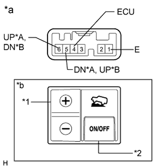
Text in Illustration *A for LHD *B for RHD *1 Speed Selector Switch *2 ON/OFF Switch *a Component without harness connected
(Crawl Control Switch)
*b Illustration shows switch from LHD vehicles Measure the resistance according to the value(s) in the table below.
Standard Resistance for LHD Tester Connection Switch Condition Specified Condition 6 (UP) - 1 (E) + Below 1 Ω FREE 10 kΩ or higher 5 (DN) - 1 (E) - Below 1 Ω FREE 10 kΩ or higher 4 (ECU) - 1 (E) ON/OFF: Pressed Below 1 Ω ON/OFF: Not pressed 10 kΩ or higher for RHD Tester Connection Switch Condition Specified Condition 5 (UP) - 1 (E) + Below 1 Ω FREE 10 kΩ or higher 6 (DN) - 1 (E) - Below 1 Ω FREE 10 kΩ or higher 4 (ECU) - 1 (E) ON/OFF: Pressed Below 1 Ω ON/OFF: Not pressed 10 kΩ or higher
NG
REPLACE CRAWL CONTROL SWITCH Click here
OK
REPLACE DRIVING SUPPORT SWITCH CONTROL ECU Click here
-