VEHICLE STABILITY CONTROL SYSTEM (for Vacuum Brake Booster) TEST MODE PROCEDURE

-
TEST MODE PROCEDURE (SIGNAL CHECK)
Note
-
After replacing the brake actuator assembly and/or yaw rate and acceleration sensor, perform calibration.
-
VSC is prohibited during test mode.
Tech Tips
-
If the ignition switch is turned from ON to ACC or off during test mode (signal check), DTCs stored during the sensor check are cleared.
-
During test mode (signal check), the skid control ECU stores all DTCs detected in the sensor check. By performing test mode (signal check), the codes are cleared if a normal condition is confirmed. The remaining codes are the codes indicating where an abnormality was found.
-
Enter test mode (when using intelligent tester).
-
Turn the ignition switch off.
-
Check that the steering wheel is centered.
-
for Manual Transmission:
Check that the shift lever is in neutral and apply the parking brake.
for Automatic Transmission:
Check that the shift lever is in P.
-
Connect the intelligent tester to the DLC3.
-
Turn the ignition switch to ON.
-
Turn the intelligent tester on.
-
Enter the following menus: Chassis / ABS/VSC/TRC / Signal Check.
-
Check that the ABS warning light and slip indicator light come on for several seconds and then blink in the test mode pattern (0.125 seconds on and 0.125 seconds off).
-
-
Enter test mode (when using SST check wire).
-
Turn the ignition switch off.
-
Check that the steering wheel is centered.
-
for Manual Transmission:
Check that the shift lever is in neutral and apply the parking brake.
for Automatic Transmission:
Check that the shift lever is in P.
-
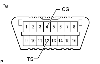
Text in Illustration *a Front view of DLC3 Using SST, connect terminals 12 (TS) and 4 (CG) of the DLC3.
- SST
- 09843-18040
-
Turn the ignition switch to ON.
-
Check that the ABS warning light and slip indicator light blink in the test mode pattern (0.125 seconds on and 0.125 seconds off).
-
Tech Tips
If the ABS warning light and slip indicator light do not blink, inspect the TS and CG terminal circuit and ABS warning light and slip indicator light circuits.
Trouble Area See procedure TS and CG terminal circuit ABS warning light circuit (Remains on) ABS warning light circuit (Does not come on) Slip indicator light circuit (Remains on) Slip indicator light circuit (Does not come on) -
-
ABS SIGNAL CHECK
-
Acceleration Sensor Check
-
Keep the vehicle stationary on a level surface for 1 second or more.
Tech Tips
The acceleration sensor check can be performed with the master cylinder pressure sensor check below.
-
-
Lost Booster Pressure Judgment Check and Master Cylinder Pressure Sensor Zero Point Calibration
Note
Perform a check in the lost booster pressure state (vacuum in the booster is depressurized).
-
Release the parking brake.
-
Turn the ignition switch to ON.
-
Check that the brake warning light comes on when depressing the brake pedal with a force of more than 59 N (6 kgf, 13.2 lbf) for 1 second or more (the lost booster pressure state is judged as normal).
-
Start the engine while depressing the brake pedal with a force of more than 59 N (6 kgf, 13.2 lbf) for 1 second or more.
-
Check that the brake warning light goes off when quickly releasing the brake pedal (the lost booster pressure state is judged as normal).
-
Leave the vehicle for 1 second or more (master cylinder pressure sensor zero point calibration).
Note
-
If depressing the brake pedal slowly or repeatedly, the master cylinder pressure sensor zero point calibration is not performed normally.
-
If the lost booster pressure judgment check results are not normal, the master cylinder pressure sensor check cannot be performed.
-
If rechecking after the engine has started, end test mode, enter test mode again, and then release vacuum in the booster by pumping the brake pedal prior to rechecking.
-
-
-
Master Cylinder Pressure Sensor Check
-
With the vehicle stationary, release the brake pedal for 1 second or more, and then quickly depress and hold the brake pedal with a force of 98 N (10 kgf, 22 lbf) or more for 1 second.
-
Check that the ABS warning light stays on for 3 seconds.
Tech Tips
-
Make sure that the ABS warning light comes on.
-
While the ABS warning light is on, continue to depress the brake pedal with a force of 98 N (10 kgf, 22 lbf) or more.
-
The ABS warning light comes on for 3 seconds every time the brake pedal operation above is performed.
-
If the master cylinder pressure sensor check is not completed, depressing the brake pedal causes further decreases in vacuum in the brake booster, making the sensor check difficult to complete.
-
If the vacuum is insufficient, the master cylinder pressure sensor check may not be completed. In this case, run the engine at idle to obtain sufficient vacuum.
-
If the brake pedal is strongly depressed when the vacuum is insufficient, the brake warning light may come on in accordance with booster pressure control. In this case, run the engine at idle to obtain sufficient vacuum.
-
-
-
Center Differential Lock Detection Switch Check
-
Set the transfer position switch to the H4L position to lock the center differential.
Tech Tips
Move the vehicle either forward or backward a little to lock the center differential.
-
Set the transfer position switch to the H4F position to unlock the center differential.
-
-
Speed Sensor Check
Note
-
Before performing the speed sensor signal check, complete the acceleration sensor and master cylinder pressure sensor checks.
-
The speed sensor check may not be completed if the speed sensor check is started while turning the steering wheel or spinning the wheels.
-
After the ABS warning light goes off, if the vehicle speed exceeds 80 km/h (50 mph), a sensor check code is stored again. Decelerate or stop the vehicle before the speed reaches 80 km/h (50 mph).
-
If the sensor check is not completed, the ABS warning light blinks while driving and the ABS does not operate.
-
Drive the vehicle straight-ahead.
Accelerate the vehicle to a speed of 45 km/h (28 mph) or more for several seconds (forward signal check).
-
Check that the ABS warning light goes off.
Tech Tips
-
The sensor check may not be completed if wheelspin occurs.
-
The ABS warning light blinks when the sensor check is completed and the brake pedal is depressed.
-
The ABS warning light comes on immediately if a malfunction is detected during the speed sensor check.
-
-
Drive the vehicle in reverse for more than 1 second at 3 km/h (2 mph) or more (reverse signal check).
-
Check that the ABS warning light goes off.
Tech Tips
Drive the vehicle in reverse and check the speed sensor signal. Note that the signal check cannot be completed if the vehicle speed is 45 km/h (28 mph) or more.
-
Stop the vehicle.
Tech Tips
When the sensor check is completed, the ABS warning light goes off while driving and blinks in the test mode pattern while the vehicle is stationary.
-
-
-
END OF SIGNAL CHECK
-
If the signal check is completed, the ABS warning light and slip indicator light blink (0.125 seconds on and 0.125 seconds off) when the vehicle stops and the ABS warning light and slip indicator light are off while the vehicle is being driven.
Note
-
When the yaw rate sensor, acceleration sensor, speed sensor, and master cylinder pressure sensor checks are completed, the signal check is completed.
-
If the signal check is not completed, the ABS warning light blinks while driving and the ABS does not operate.
-
-
-
READ DTC OF SIGNAL CHECK FUNCTION
-
When using the intelligent tester:
-
Read the output DTC(s) by following the tester screen.
Note
-
If only DTCs other than test mode sensor check DTCs are output, repair the malfunctions and clear the DTCs.
-
If test mode (signal check) DTCs and other DTCs are output or if only test mode (signal check) DTCs are output, repair the malfunctions, clear the DTCs, and perform the test mode (signal check) inspection again.
Tech Tips
Refer to Signal Check DTCs.
-
-
Turn the ignition switch off and disconnect the intelligent tester.
-
-
When using SST check wire:
-
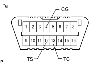
Text in Illustration *a Front view of DLC3 Using SST, connect terminals 12 (TS), 13 (TC) and 4 (CG) of the DLC3.
- SST
- 09843-18040
-
Count the number of blinks of the ABS warning light and slip indicator lights.
Note
-
If only DTCs other than test mode sensor check DTCs are output, repair the malfunctions and clear the DTCs.
-
If test mode (signal check) DTCs and other DTCs are output or if only test mode (signal check) DTCs are output, repair the malfunctions, clear the DTCs, and perform the test mode (signal check) inspection again.
Tech Tips
-
If more than 1 malfunction is detected at the same time, the lowest numbered code is output first.
-
Refer to the list of test mode DTCs.
-
-
Disconnect SST from terminals 12 (TS), 4 (CG) and 13 (TC) of the DLC3 and turn the ignition switch off.
-
Turn the ignition switch to ON.
Tech Tips
-
If the ignition switch is not turned to ON after SST is removed from the DLC3, the previous test mode continues.
-
If the ignition switch is turned to ON with terminals TS and CG connected, the previous test mode continues.
-
-
-
-
LIST OF TEST MODE (SIGNAL CHECK) DTC
Tech Tips
The codes in this table are output only in test mode (signal check).
ABS Sensor DTC Code Detection Item Trouble Area Intelligent Tester Display ABS Warning Light Display C1271 71 Low output signal from front speed sensor RH
-
Front speed sensor RH
-
Sensor installation
-
Speed sensor rotor
C1272 72 Low output signal from front speed sensor LH
-
Front speed sensor LH
-
Sensor installation
-
Speed sensor rotor
C1273 73 Low output signal from rear speed sensor RH
-
Rear speed sensor RH
-
Sensor installation
-
Speed sensor rotor
C1274 74 Low output signal from rear speed sensor LH
-
Rear speed sensor LH
-
Sensor installation
-
Speed sensor rotor
C1275 75 Abnormal change in output signal from front speed sensor RH Speed sensor rotor C1276 76 Abnormal change in output signal from front speed sensor LH Speed sensor rotor C1277 77 Abnormal change in output signal from rear speed sensor RH Speed sensor rotor C1278 78 Abnormal change in output signal from rear speed sensor LH Speed sensor rotor C1279 79 Acceleration sensor output voltage malfunction
-
Yaw rate and acceleration sensor
-
Sensor installation
C1281 81 Master cylinder pressure sensor output malfunction
-
Stop light switch
-
Stop light switch circuit
-
Brake actuator assembly (Master cylinder pressure)
C1282 82 Center differential lock position switch malfunction
-
Harness or connector
-
Transfer system
-
Brake actuator assembly (Skid control ECU)
-