VEHICLE STABILITY CONTROL SYSTEM (for Hydraulic Brake Booster), Diagnostic DTC:C1379

| DTC Code | DTC Name |
|---|---|
| C1379 | Downhill Assist Control Switch Malfunction (Test Mode DTC) |
DESCRIPTION
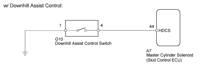
w/ Downhill Assist Control:
DTC C1379 is cleared when the downhill assist control switch sends a downhill assist control operation signal or when test mode ends.
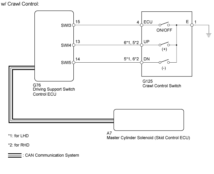
w/ Crawl Control:
DTC C1379 is cleared when the crawl control switch sends a crawl control operation signal or when test mode ends.
| DTC Code | DTC Detection Condition | Trouble Area |
|---|---|---|
| C1379 | Stored only during test mode. |
|
WIRING DIAGRAM
INSPECTION PROCEDURE
Note
When replacing the master cylinder solenoid, perform calibration Click here.
PROCEDURE
-
CONFIRM VEHICLE SPECIFICATIONS
-
Confirm the vehicle specifications.
Result Result Proceed to w/ Downhill Assist Control A w/ Crawl Control B
B 
CHECK CAN BUS Click here
A 
-
-
READ VALUE USING INTELLIGENT TESTER (DOWNHILL ASSIST CONTROL SW)
-
Turn the ignition switch off.
-
Connect the intelligent tester to the DLC3.
-
Turn the ignition switch to ON.
-
Turn the intelligent tester on.
-
Enter the following menus: Chassis / ABS/VSC/TRC / Data List.
-
Check the Data List for proper functioning of the downhill assist control switch.
ABS/VSC/TRC Tester Display Measurement Item/Range Normal Condition Diagnostic Note Downhill Assist Control SW Downhill assist control switch / ON or OFF ON: Downhill assist control on
OFF: Downhill assist control off
- OK The intelligent tester displays ON or OFF according to downhill assist control switch operation.
NG
OK
-
-
CHECK TEST MODE DTC
-
Perform the downhill assist control switch check in the Test Mode Procedure Click here.
OK Test mode DTC C1379 is cleared. Result Result Proceed to OK A NG (for LHD) B NG (for RHD) C
B 
REPLACE MASTER CYLINDER SOLENOID Click here
C
REPLACE MASTER CYLINDER SOLENOID Click here
A 
USE SIMULATION METHOD TO CHECK Click here
-
-
INSPECT DOWNHILL ASSIST CONTROL SWITCH
-
Remove the downhill assist control switch Click here.
-
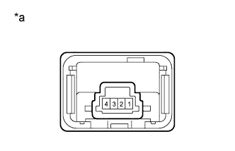
Text in Illustration *a Component without harness connected
(Downhill Assist Control Switch)
Measure the resistance according to the value(s) in the table below.
Standard Resistance Tester Connection Switch Condition Specified Condition 1 - 4 Not pushed in 10 kΩ or higher Pushed in Below 1 Ω
NG
REPLACE DOWNHILL ASSIST CONTROL SWITCH Click here
OK
-
-
CHECK HARNESS AND CONNECTOR (SKID CONTROL ECU - DOWNHILL ASSIST CONTROL SWITCH)
-
Disconnect the A7 skid control ECU connector.
-
Disconnect the G10 downhill assist control switch connector.
-
Measure the resistance according to the value(s) in the table below.
Standard Resistance Tester Connection Condition Specified Condition A7-44 (HDCS) - G10-4 Always Below 1 Ω A7-44 (HDCS) - Body ground Always 10 kΩ or higher G10-1 - Body ground Always Below 1 Ω Result Result Proceed to NG A OK (for LHD) B OK (for RHD) C
B
REPLACE MASTER CYLINDER SOLENOID Click here
C
REPLACE MASTER CYLINDER SOLENOID Click here
A
REPAIR OR REPLACE HARNESS OR CONNECTOR
-
-
CHECK CAN BUS
-
Check that there are no problems with the CAN communication system (for LHD: Click here, for RHD: Click here.
Result Result Proceed to OK A NG (for LHD) B NG (for RHD) C
B
GO TO CAN COMMUNICATION SYSTEM (HOW TO PROCEED WITH TROUBLESHOOTING) Click here
C
GO TO CAN COMMUNICATION SYSTEM (HOW TO PROCEED WITH TROUBLESHOOTING) Click here
A
-
-
READ VALUE USING INTELLIGENT TESTER (CRAWL CONTROL SWITCH)
-
Turn the ignition switch off.
-
Connect the intelligent tester to the DLC3.
-
Turn the ignition switch to ON.
-
Turn the intelligent tester on.
-
Enter the following menus: Body Electrical / D-SEAT SW / Data List.
-
Check the Data List for proper functioning of the crawl control switch.
D-SEAT SW Tester Display Measurement Item/Range Normal Condition Diagnostic Note Crawl Control Main Switch Crawl control switch (ON/OFF switch)/ ON or OFF ON: Crawl control on
OFF: Crawl control off
- Crawl Control Up Switch Crawl Control Switch (Speed selector switch up side)/ ON or OFF ON: Speed selector switch up side pushed and held
OFF: Speed selector switch up side not pushed
- Crawl Control Down Switch Crawl Control Switch (Speed selector switch down side)/ ON or OFF ON: Speed selector switch down side pushed and held
OFF: Speed selector switch down side not pushed
- OK The intelligent tester displays according to crawl control switch operation.
NG
CHECK HARNESS AND CONNECTOR (CRAWL CONTROL SWITCH - DRIVING SUPPORT SWITCH CONTROL ECU) Click here
OK
-
-
CHECK TEST MODE DTC
-
Perform the crawl control switch check in the Test Mode Procedure Click here.
OK Test mode DTC C1379 is cleared. Result Result Proceed to OK A NG (for LHD) B NG (for RHD) C
B
REPLACE MASTER CYLINDER SOLENOID Click here
C
REPLACE MASTER CYLINDER SOLENOID Click here
A
USE SIMULATION METHOD TO CHECK Click here
-
-
CHECK HARNESS AND CONNECTOR (CRAWL CONTROL SWITCH - DRIVING SUPPORT SWITCH CONTROL ECU)
-
Disconnect the G125 crawl control switch connector.
-
Disconnect the G76 driving support switch control ECU connector.
-
Measure the resistance according to the value(s) in the table below.
Standard Resistance for LHD Tester Connection Condition Specified Condition G125-4 (ECU) - G76-15 (SWI3) Always Below 1 Ω G125-4 (ECU) - Body ground Always 10 kΩ or higher G125-6 (UP) - G76-13 (SWI4) Always Below 1 Ω G125-6 (UP) - Body ground Always 10 kΩ or higher G125-5 (DN) - G76-14 (SWI5) Always Below 1 Ω G125-5 (DN) - Body ground Always 10 kΩ or higher G125-1 (E) - Body ground Always Below 1 Ω for RHD Tester Connection Condition Specified Condition G125-4 (ECU) - G76-15 (SWI3) Always Below 1 Ω G125-4 (ECU) - Body ground Always 10 kΩ or higher G125-5 (UP) - G76-13 (SWI4) Always Below 1 Ω G125-5 (UP) - Body ground Always 10 kΩ or higher G125-6 (DN) - G76-14 (SWI5) Always Below 1 Ω G125-6 (DN) - Body ground Always 10 kΩ or higher G125-1 (E) - Body ground Always Below 1 Ω
NG
REPAIR OR REPLACE HARNESS OR CONNECTOR
OK
-
-
INSPECT CRAWL CONTROL SWITCH
-
Remove the crawl control switch Click here.
-
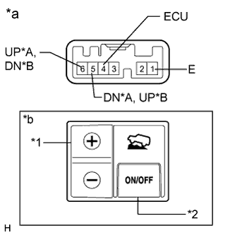
Text in Illustration *A for LHD *B for RHD *1 Speed Selector Switch *2 ON/OFF Switch *a Component without harness connected
(Crawl Control Switch)
*b Illustration shows switch from LHD vehicles Measure the resistance according to the value(s) in the table below.
Standard Resistance for LHD Tester Connection Switch Condition Specified Condition 6 (UP) - 1 (E) + Below 1 Ω FREE 10 kΩ or higher 5 (DN) - 1 (E) - Below 1 Ω FREE 10 kΩ or higher 4 (ECU) - 1 (E) ON/OFF: Pressed Below 1 Ω ON/OFF: Not pressed 10 kΩ or higher for RHD Tester Connection Switch Condition Specified Condition 5 (UP) - 1 (E) + Below 1 Ω FREE 10 kΩ or higher 6 (DN) - 1 (E) - Below 1 Ω FREE 10 kΩ or higher 4 (ECU) - 1 (E) ON/OFF: Pressed Below 1 Ω ON/OFF: Not pressed 10 kΩ or higher
NG
REPLACE CRAWL CONTROL SWITCH Click here
OK
REPLACE DRIVING SUPPORT SWITCH CONTROL ECU Click here
-