VEHICLE STABILITY CONTROL SYSTEM (for Hydraulic Brake Booster), Diagnostic DTC:C1340

| DTC Code | DTC Name |
|---|---|
| C1340 | Center Differential Lock Circuit |
DESCRIPTION
| DTC Code | DTC Detection Condition | Trouble Area |
|---|---|---|
| C1340 | An open circuit is detected in the EXI circuit of the skid control ECU. |
|
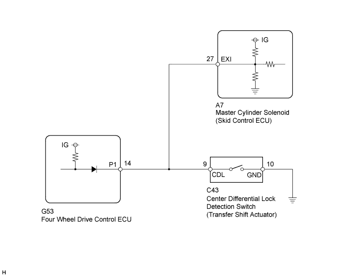
WIRING DIAGRAM
INSPECTION PROCEDURE
Note
When replacing the master cylinder solenoid, perform calibration Click here.
PROCEDURE
-
CHECK TERMINAL VOLTAGE (EXI)
-
Disconnect the A7 skid control ECU connector.
-
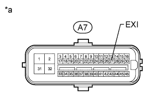
Text in Illustration *a Front view of wire harness connector
(to Skid Control ECU)
Measure the voltage according to the value(s) in the table below.
Standard Voltage Tester Connection Switch Condition Specified Condition A7-27 (EXI) - Body ground Ignition switch ON 11 to 14 V
NG 
OK 
-
-
RECONFIRM DTC
-
Clear the DTCs Click here.
-
Check for DTCs Click here.
Result Result Proceed to DTC is not output A DTC is output (for LHD) B DTC is output (for RHD) C
B 
REPLACE MASTER CYLINDER SOLENOID Click here
C
REPLACE MASTER CYLINDER SOLENOID Click here
A 
USE SIMULATION METHOD TO CHECK Click here
-
-
CHECK HARNESS AND CONNECTOR (SKID CONTROL ECU - FOUR WHEEL DRIVE CONTROL ECU/TRANSFER SHIFT ACTUATOR)
-
Disconnect the A7 skid control ECU connector.
-
Disconnect the G53 four wheel drive control ECU connector.
-
Disconnect the C43 transfer shift actuator connector.
-
Measure the resistance according to the value(s) in the table below.
Standard Resistance Tester Connection Condition Specified Condition A7-27 (EXI) - G53-14 (P1) Always Below 1 Ω A7-27 (EXI) - C43-9 (CDL) Always Below 1 Ω A7-27 (EXI) - Body ground Always 10 kΩ or higher
NG
REPAIR OR REPLACE HARNESS OR CONNECTOR
OK
GO TO TRANSFER SYSTEM (PROBLEM SYMPTOMS TABLE) Click here
-