VEHICLE STABILITY CONTROL SYSTEM (for Hydraulic Brake Booster) CALIBRATION

-
DESCRIPTION
-
After replacing VSC-related components, clearing and reading the sensor calibration data is necessary.
-
Follow the chart to perform calibration.
Part Replaced Necessary Operation Master Cylinder Solenoid (Skid Control ECU)
-
Clearing zero point calibration data and information about whether kinetic dynamic suspension system exists
-
Yaw rate and acceleration sensor zero point calibration
-
Steering angle sensor zero point calibration
-
Acquiring information on whether kinetic dynamic suspension system exists
-
Downhill assist control calibration (w/ Downhill Assist Control)
-
Crawl control calibration (w/ Crawl Control)
Yaw Rate and Acceleration Sensor
-
Clearing zero point calibration data and information about whether kinetic dynamic suspension system exists
-
Yaw rate and acceleration sensor zero point calibration
-
Steering angle sensor zero point calibration
-
Acquiring information on whether kinetic dynamic suspension system exists
-
Downhill assist control calibration (w/ Downhill Assist Control)
-
Crawl control calibration (w/ Crawl Control)
Spiral Cable Sub-assembly (Steering Angle Sensor)
-
Clearing zero point calibration data and information about whether kinetic dynamic suspension system exists
-
Yaw rate and acceleration sensor zero point calibration
-
Steering angle sensor zero point calibration
-
Acquiring information on whether kinetic dynamic suspension system exists
-
Downhill assist control calibration (w/ Downhill Assist Control)
-
Crawl control calibration (w/ Crawl Control)
-
-
-
PERFORM YAW RATE AND ACCELERATION SENSOR AND STEERING ANGLE SENSOR ZERO POINT CALIBRATION AND ACQUIRE INFORMATION ON WHETHER KINETIC DYNAMIC SUSPENSION SYSTEM EXISTS (When Using Intelligent Tester)
Note
-
Make sure that CAN communication between the stabilizer control ECU and master cylinder solenoid (skid control ECU) is properly functioning. In "Check Installed Systems (ECUs and Sensors) That Use CAN Communication" under Diagnosis System in CAN communication system, confirm that the bus lines to the stabilizer control ECU are connected for vehicles with a kinetic dynamic suspension system and that the bus lines to the stabilizer control ECU are not connected for vehicles without a kinetic dynamic suspension system.
If calibration is performed while there is a CAN communication malfunction between the stabilizer control ECU and master cylinder solenoid (skid control ECU), the master cylinder solenoid (skid control ECU) operates as if there is no kinetic dynamic suspension system even if the vehicle is equipped with one.
-
If information about whether the kinetic dynamic suspension system exists is not acquired, the slip indicator light illuminates and the vehicle stability control system does not operate.
-
In order to acquire information about whether the kinetic dynamic suspension system exists, put the system in test mode and leave the vehicle stationary for 7 seconds or more.
-
While obtaining the zero points, keep the vehicle stationary and do not vibrate, tilt, move, or shake it (do not start the engine).
-
Be sure to perform this procedure on a level surface (with an inclination of less than 1%).
-
Clear the zero point calibration data and information about whether the kinetic dynamic suspension system exists.
-
Turn the ignition switch off.
-
Check that the steering wheel is centered.
-
for Manual Transmission:
Check that the shift lever is in neutral and apply the parking brake.
for Automatic Transmission:
Check that the shift lever is in P.
-
Connect the intelligent tester to the DLC3.
-
Turn the ignition switch to ON.
-
Turn the intelligent tester on.
-
Enter the following menus: Chassis / ABS/VSC/TRC / Utility / Reset Memory.
-
Turn the ignition switch off.
-
-
Perform zero point calibration and acquire information about whether the kinetic dynamic suspension system exists.
-
Turn the ignition switch off.
-
Check that the steering wheel is centered.
-
for Manual Transmission:
Check that the shift lever is in neutral and apply the parking brake.
for Automatic Transmission:
Check that the shift lever is in P.
Note
-
DTCs C1210 (Zero Point Calibration of Yaw Rate Sensor Undone), C1336 (Zero Point Calibration of Acceleration Sensor Undone) and C120A (ECU Initial Setting Incomplete) are stored if the shift lever is not in P (for Automatic Transmission) or the parking brake is not applied (for Manual Transmission).
-
If a DTC is output that indicates zero point calibration is incomplete, repeat the procedure starting at the step for clearing the zero point calibration data and system information.
-
-
Connect the intelligent tester to the DLC3.
-
Turn the ignition switch to ON.
-
Turn the intelligent tester on.
-
Enter the following menus: Chassis / ABS/VSC/TRC / Utility / Test Mode.
-
With the ignition switch turned to ON, keep the vehicle stationary on a level surface for 7 seconds or more.
-
Check that the slip indicator light comes on for several seconds and then blinks in the test mode pattern (0.125 seconds on and 0.125 seconds off).
Tech Tips
-
If the slip indicator light does not blink, perform zero point calibration again.
-
The zero point calibration is performed only once after the system enters test mode.
-
Calibration cannot be performed again until the stored data is cleared.
-
-
Turn the ignition switch off and disconnect the intelligent tester.
-
Drive the vehicle straight ahead at 40 km/h (25 mph) or more for at least 10 seconds.
-
-
-
PERFORM YAW RATE AND ACCELERATION SENSOR AND STEERING ANGLE SENSOR ZERO POINT CALIBRATION AND ACQUIRE INFORMATION ON WHETHER KINETIC DYNAMIC SUSPENSION SYSTEM EXISTS (When Using SST Check Wire)
Note
-
Make sure that CAN communication between the stabilizer control ECU and master cylinder solenoid (skid control ECU) is properly functioning. In "Check Installed Systems (ECUs and Sensors) That Use CAN Communication" under Diagnosis System in CAN communication system, confirm that the bus lines to the stabilizer control ECU are connected for vehicles with a kinetic dynamic suspension system and that the bus lines to the stabilizer control ECU are not connected for vehicles without a kinetic dynamic suspension system.
If calibration is performed while there is a CAN communication malfunction between the stabilizer control ECU and master cylinder solenoid (skid control ECU), the master cylinder solenoid (skid control ECU) operates as if there is no kinetic dynamic suspension system even if the vehicle is equipped with one.
-
If information about whether the kinetic dynamic suspension system exists is not acquired, the slip indicator light illuminates and the vehicle stability control system does not operate.
-
In order to acquire information about whether the kinetic dynamic suspension system exists, put the system in test mode and leave the vehicle stationary for 7 seconds or more.
-
While obtaining the zero points, keep the vehicle stationary and do not vibrate, tilt, move, or shake it (do not start the engine).
-
Be sure to perform this procedure on a level surface (with an inclination of less than 1%).
-
Clear the zero point calibration data and information about whether the kinetic dynamic suspension system exists.
-
Turn the ignition switch off.
-
Check that the steering wheel is centered.
-
for Manual Transmission:
Check that the shift lever is in neutral and apply the parking brake.
for Automatic Transmission:
Check that the shift lever is in P.
-
Turn the ignition switch to ON.
-
The ABS warning light and slip indicator light come on for 3 seconds to indicate that the initial check is completed.
-
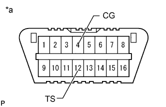
Text in Illustration *a Front view of DLC3 Using SST, connect and disconnect terminals 12 (TS) and 4 (CG) of the DLC3 4 times or more within 8 seconds.
- SST
- 09843-18040
-
Check that the slip indicator light comes on.
-
-
Perform zero point calibration and acquire information about whether the kinetic dynamic suspension system exists.
-
Turn the ignition switch off.
-
Check that the steering wheel is centered.
-
for Manual Transmission:
Check that the shift lever is in neutral and apply the parking brake.
for Automatic Transmission:
Check that the shift lever is in P.
Note
-
DTCs 36 (Zero Point Calibration of Yaw Rate Sensor Undone), 39 (Zero Point Calibration of Acceleration Sensor Undone) and 13 (ECU Initial Setting Incomplete) are stored if the shift lever is not in P (for Automatic Transmission) or the parking brake is not applied (for Manual Transmission).
-
If a DTC is output that indicates zero point calibration is incomplete, repeat the procedure starting at the step for clearing the zero point calibration data and system information.
-
-
Text in Illustration *a Front view of DLC3 Using SST, connect terminals 12 (TS) and 4 (CG) of the DLC3.
- SST
- 09843-18040
-
Turn the ignition switch to ON.
-
With the ignition switch turned to ON, keep the vehicle stationary on a level surface for 7 seconds or more.
-
Check that the slip indicator light comes on for several seconds and then blinks in the test mode pattern (0.125 seconds on and 0.125 seconds off).
Tech Tips
-
If the slip indicator light does not blink, perform zero point calibration again.
-
The zero point calibration is performed only once after the system enters test mode.
-
Calibration cannot be performed again until the stored data is cleared.
-
-
Turn the ignition switch off and disconnect SST from the DLC3.
-
Drive the vehicle straight ahead at 40 km/h (25 mph) or more for at least 10 seconds.
-
-
-
PERFORM DOWNHILL ASSIST CONTROL CALIBRATION (w/ Downhill Assist Control)
-
Enter test mode (when using the intelligent tester).
-
Turn the ignition switch off.
-
Connect the intelligent tester to the DLC3.
-
Turn the ignition switch to ON.
-
Turn the intelligent tester on.
-
Enter the following menus: Chassis / ABS/VSC/TRC / Utility / Test Mode.
-
-
Enter test mode (when using SST check wire).
-
Turn the ignition switch off.
-
Text in Illustration *a Front view of DLC3 Using SST, connect terminals 12 (TS) and 4 (CG) of the DLC3.
- SST
- 09843-18040
-
Turn the ignition switch to ON.
-
-
Turn the downhill assist control switch off.
-
Push the downhill assist control switch and check that the downhill assist control indicator light is blinking.
-
Turn the downhill assist control switch off.
-
Turn the ignition switch off.
-
Check if DTC C120A is output.
Tech Tips
If DTC C120A is not output, calibration was performed successfully.
-
-
PERFORM CRAWL CONTROL CALIBRATION (w/ Crawl Control)
-
Enter test mode (when using the intelligent tester).
-
Turn the ignition switch off.
-
Connect the intelligent tester to the DLC3.
-
Turn the ignition switch to ON.
-
Turn the intelligent tester on.
-
Enter the following menus: Chassis / ABS/VSC/TRC / Utility / Test Mode.
-
-
Enter test mode (when using SST check wire).
-
Turn the ignition switch off.
-
Text in Illustration *a Front view of DLC3 Using SST, connect terminals 12 (TS) and 4 (CG) of the DLC3.
- SST
- 09843-18040
-
Turn the ignition switch to ON.
-
-
Push the ON/OFF switch and check that the crawl indicator light is on while the switch is being pushed.
-
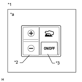
Text in Illustration *1 Crawl Control Switch *2 Speed Selector Switch *3 ON/OFF Switch *a Illustration shows switch from LHD vehicles Turn the ON/OFF switch off.
-
Turn the ignition switch off.
-
Check if DTC C120A is output.
Tech Tips
If DTC C120A is not output, calibration was performed successfully.
-
-
PROCEDURES NECESSARY WHEN CABLE IS DISCONNECTED/RECONNECTED TO BATTERY TERMINAL (w/ Multi-information Display)
Note
The steering angle display on the combination meter does not appear if any of the following is performed: 1) The cable is disconnected and reconnected to the negative (-) battery terminal, 2) the steering angle sensor connector is disconnected, or 3) a fuse related to the steering angle sensor is removed.
-
Drive the vehicle straight ahead at 40 km/h (25 mph) or more for at least 10 seconds.
-
Confirm the steering angle display function.
-
Turn the steering wheel to the left and right and confirm that the steering angle display function is normal.
-
-