VEHICLE STABILITY CONTROL SYSTEM (for Hydraulic Brake Booster) CALIBRATION

-
DESCRIPTION
-
After replacing VSC-related components, clearing and reading the sensor calibration data is necessary.
-
Follow the chart to perform calibration.
Part Replaced Necessary Operation Master Cylinder Solenoid (Skid Control ECU)
-
Clearing zero point calibration data
-
Yaw rate and acceleration sensor zero point calibration
-
Steering angle sensor zero point calibration
-
Downhill assist control calibration (w/ Downhill Assist Control)
-
Crawl control calibration (w/ Crawl Control)
Yaw Rate and Acceleration Sensor
-
Clearing zero point calibration data
-
Yaw rate and acceleration sensor zero point calibration
-
Steering angle sensor zero point calibration
-
Downhill assist control calibration (w/ Downhill Assist Control)
-
Crawl control calibration (w/ Crawl Control)
Spiral Cable Sub-assembly (Steering Angle Sensor)
-
Clearing zero point calibration data
-
Yaw rate and acceleration sensor zero point calibration
-
Steering angle sensor zero point calibration
-
Downhill assist control calibration (w/ Downhill Assist Control)
-
Crawl control calibration (w/ Crawl Control)
-
-
-
PERFORM YAW RATE AND ACCELERATION SENSOR AND STEERING ANGLE SENSOR ZERO POINT CALIBRATION (When Using Intelligent Tester)
Note
-
While obtaining the zero points, keep the vehicle stationary and do not vibrate, tilt, move, or shake it (do not start the engine).
-
Be sure to perform this procedure on a level surface (with an inclination of less than 1%).
-
Clear the zero point calibration data.
-
Turn the ignition switch off.
-
Check that the steering wheel is centered.
-
for Manual Transmission:
Check that the shift lever is in neutral and apply the parking brake.
for Automatic Transmission:
Check that the shift lever is in P.
-
Connect the intelligent tester to the DLC3.
-
Turn the ignition switch to ON.
-
Turn the intelligent tester on.
-
Enter the following menus: Chassis / ABS/VSC/TRC / Utility / Reset Memory.
-
Turn the ignition switch off.
-
-
Perform zero point calibration of the yaw rate and acceleration sensor.
-
Turn the ignition switch off.
-
Check that the steering wheel is centered.
-
for Manual Transmission:
Check that the shift lever is in neutral and apply the parking brake.
for Automatic Transmission:
Check that the shift lever is in P.
Note
-
DTCs C1210 (Zero Point Calibration of Yaw Rate Sensor Undone) and C1336 (Zero Point Calibration of Acceleration Sensor Undone) are stored if the shift lever is not in P (for Automatic Transmission) or the parking brake is not applied (for Manual Transmission).
-
If a DTC is output that indicates zero point calibration is incomplete, repeat the procedure starting at the step for clearing the zero point calibration data and system information.
-
-
Connect the intelligent tester to the DLC3.
-
Turn the ignition switch to ON.
-
Turn the intelligent tester on.
-
Enter the following menus: Chassis / ABS/VSC/TRC / Utility / Test Mode.
-
Keep the vehicle stationary on a level surface for 5 seconds or more.
-
Check that the slip indicator light comes on for several seconds and then blinks in the test mode pattern (0.125 seconds on and 0.125 seconds off).
Tech Tips
-
If the slip indicator light does not blink, perform zero point calibration again.
-
The zero point calibration is performed only once after the system enters test mode.
-
Calibration cannot be performed again until the stored data is cleared.
-
-
Turn the ignition switch off and disconnect the intelligent tester.
-
Drive the vehicle straight ahead at 40 km/h (25 mph) or more for at least 10 seconds.
-
-
-
PERFORM YAW RATE AND ACCELERATION SENSOR AND STEERING ANGLE SENSOR ZERO POINT CALIBRATION (When Using SST Check Wire)
Note
-
While obtaining the zero points, keep the vehicle stationary and do not vibrate, tilt, move, or shake it (do not start the engine).
-
Be sure to perform this procedure on a level surface (with an inclination of less than 1%).
-
Clear the zero point calibration data.
-
Turn the ignition switch off.
-
Check that the steering wheel is centered.
-
for Manual Transmission:
Check that the shift lever is in neutral and apply the parking brake.
for Automatic Transmission:
Check that the shift lever is in P.
-
Turn the ignition switch to ON.
-
The ABS warning light and slip indicator light come on for 3 seconds to indicate that the initial check is completed.
-
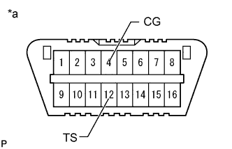
Text in Illustration *a Front view of DLC3 Using SST, connect and disconnect terminals 12 (TS) and 4 (CG) of the DLC3 4 times or more within 8 seconds.
- SST
- 09843-18040
-
Check that the slip indicator light comes on.
-
-
Perform zero point calibration of the yaw rate and acceleration sensor.
-
Turn the ignition switch off.
-
Check that the steering wheel is centered.
-
for Manual Transmission:
Check that the shift lever is in neutral and apply the parking brake.
for Automatic Transmission:
Check that the shift lever is in P.
Note
-
DTCs 36 (Zero Point Calibration of Yaw Rate Sensor Undone) and 39 (Zero Point Calibration of Acceleration Sensor Undone) are stored if the shift lever is not in P (for Automatic Transmission) or the parking brake is not applied (for Manual Transmission).
-
If a DTC is output that indicates zero point calibration is incomplete, repeat the procedure starting at the step for clearing the zero point calibration data and system information.
-
-
Text in Illustration *a Front view of DLC3 Using SST, connect terminals 12 (TS) and 4 (CG) of the DLC3.
- SST
- 09843-18040
-
Turn the ignition switch to ON.
-
Keep the vehicle stationary on a level surface for 5 seconds or more.
-
Check that the slip indicator light comes on for several seconds and then blinks in the test mode pattern (0.125 seconds on and 0.125 seconds off).
Tech Tips
-
If the slip indicator light does not blink, perform zero point calibration again.
-
The zero point calibration is performed only once after the system enters test mode.
-
Calibration cannot be performed again until the stored data is cleared.
-
-
Turn the ignition switch off and disconnect SST from the DLC3.
-
Drive the vehicle straight ahead at 40 km/h (25 mph) or more for at least 10 seconds.
-
-
-
PERFORM DOWNHILL ASSIST CONTROL CALIBRATION (w/ Downhill Assist Control)
-
Enter test mode (when using the intelligent tester).
-
Turn the ignition switch off.
-
Connect the intelligent tester to the DLC3.
-
Turn the ignition switch to ON.
-
Turn the intelligent tester on.
-
Enter the following menus: Chassis / ABS/VSC/TRC / Utility / Test Mode.
-
-
Enter test mode (when using SST check wire).
-
Turn the ignition switch off.
-
Text in Illustration *a Front view of DLC3 Using SST, connect terminals 12 (TS) and 4 (CG) of the DLC3.
- SST
- 09843-18040
-
Turn the ignition switch to ON.
-
-
Turn the downhill assist control switch off.
-
Push the downhill assist control switch and check that the downhill assist control indicator light is blinking.
-
Turn the downhill assist control switch off.
-
Turn the ignition switch off.
-
Check if DTC C120A is output.
Tech Tips
If DTC C120A is not output, calibration was performed successfully.
-
-
PERFORM CRAWL CONTROL CALIBRATION (w/ Crawl Control)
-
Enter test mode (when using the intelligent tester).
-
Turn the ignition switch off.
-
Connect the intelligent tester to the DLC3.
-
Turn the ignition switch to ON.
-
Turn the intelligent tester on.
-
Enter the following menus: Chassis / ABS/VSC/TRC / Utility / Test Mode.
-
-
Enter test mode (when using SST check wire).
-
Turn the ignition switch off.
-
Text in Illustration *a Front view of DLC3 Using SST, connect terminals 12 (TS) and 4 (CG) of the DLC3.
- SST
- 09843-18040
-
Turn the ignition switch to ON.
-
-
Push the ON/OFF switch and check that the crawl indicator light is on while the switch is being pushed.
-
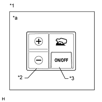
Text in Illustration *1 Crawl Control Switch *2 Speed Selector Switch *3 ON/OFF Switch *a Illustration shows switch from LHD vehicles Turn the ON/OFF switch off.
-
Turn the ignition switch off.
-
Check if DTC C120A is output.
Tech Tips
If DTC C120A is not output, calibration was performed successfully.
-
-
PROCEDURES NECESSARY WHEN CABLE IS DISCONNECTED/RECONNECTED TO BATTERY TERMINAL (w/ Multi-information Display)
Note
The steering angle display on the combination meter does not appear if any of the following is performed: 1) The cable is disconnected and reconnected to the negative (-) battery terminal, 2) the steering angle sensor connector is disconnected, or 3) a fuse related to the steering angle sensor is removed.
-
Drive the vehicle straight ahead at 40 km/h (25 mph) or more for at least 10 seconds.
-
Confirm the steering angle display function.
-
Turn the steering wheel to the left and right and confirm that the steering angle display function is normal.
-
-